Wstęp
Welcome to the ULTRICS Digital Multimeter D2 user manual. This device is designed for precise and reliable electrical measurements, suitable for professionals and DIY enthusiasts. It accurately measures AC/DC voltage, DC current, resistance, continuity, and diodes. This manual provides essential information for safe and effective operation, helping you to maximize the utility of your new multimeter.
Informacje dotyczące bezpieczeństwa
OSTRZEŻENIE: Always exercise extreme caution when working with electrical circuits. Improper use of this multimeter can result in electric shock, personal injury, or damage to the device.
- Nie należy przekraczać maksymalnych wartości wejściowych w żadnym zakresie.
- Do not use the multimeter if it or the test leads appear damaged. Inspect them before each use.
- Ensure the function switch is in the correct position before making measurements. Changing ranges while connected to a live circuit can cause damage.
- Disconnect power to the circuit before measuring resistance, continuity, or diodes.
- Zachowaj ostrożność podczas pracy z objętościątagpowyżej 30 V AC RMS, 42 V szczytowo lub 60 V DC. Te wartościtages pose a significant shock hazard.
- Always connect the common (COM) test lead first, then the live lead. Disconnect the live lead first, then the common lead.
- Replace the battery when the low battery indicator appears to ensure accurate readings and proper device function.
This multimeter is rated CAT II 600V, indicating its suitability for measurements on circuits directly connected to the low-voltage instalacja.
Zawartość opakowania
Sprawdź, czy w opakowaniu znajdują się wszystkie elementy:
- 1 x ULTRICS Digital Multimeter D2
- 2 x przewody pomiarowe (czerwony i czarny)
- Bateria 1 x 9V
- 1 x Instrukcja obsługi (ten dokument)
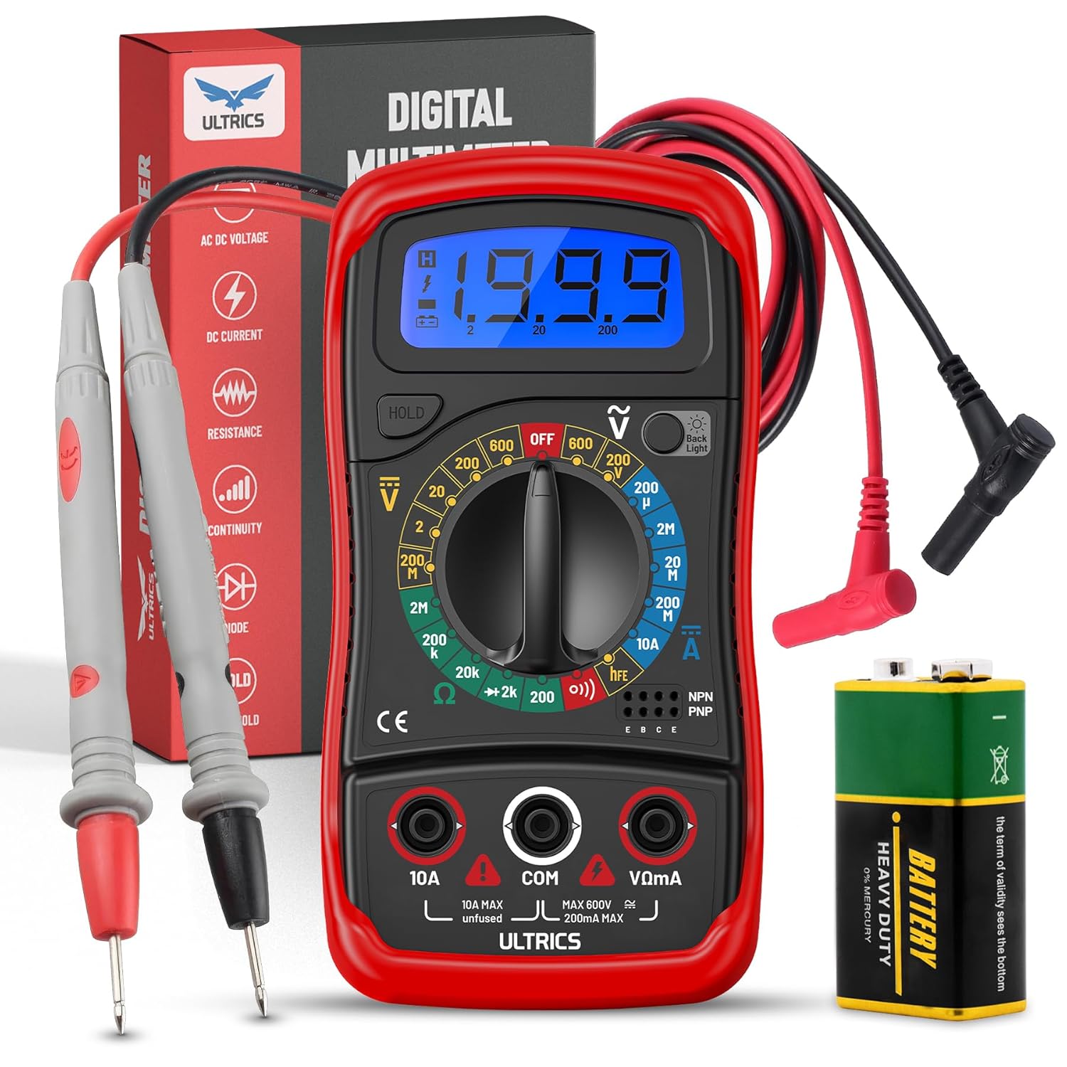
Image: Contents of the ULTRICS Digital Multimeter D2 package, including the multimeter, red and black test leads, and a 9V battery.
Produkt ponadview
Familiarize yourself with the components of your ULTRICS Digital Multimeter D2.

Image: Detailed diagram of the ULTRICS Digital Multimeter D2, highlighting its key components such as the LCD display, data hold button, backlight button, function switch, test lead jacks, and protective rubber shell.
- Wyświetlacz LCD: Shows measurement readings, units, and polarity. Features a bright backlight for low-light conditions.
- Przycisk wstrzymania danych: Freezes the current reading on the display for easier recording.
- Przycisk podświetlenia: Włącza lub wyłącza podświetlenie wyświetlacza.
- Function Switch (Rotary Dial): Wybiera żądaną funkcję pomiaru i zakres.
- Gniazdo wejściowe 10A: Used for measuring DC current up to 10 Ampsą.
- COM (Common) Input Jack: The negative (-) input for all measurements. Always connect the black test lead here.
- VΩmA Input Jack: The positive (+) input for voltage, resistance, and milliampere current measurements. Connect the red test lead here.
- Transistor Test Jacks (hFE): Used for testing NPN and PNP transistors.
- Protective Rubber Shell: Provides durability and protection against minor impacts and splashes.
- Składana podpórka: Allows for hands-free operation and easy viewkąt.
Organizować coś
Instalowanie akumulatora
The ULTRICS Digital Multimeter D2 requires one 9V battery (included).
- Znajdź komorę baterii z tyłu multimetru.
- Za pomocą śrubokręta odkręć śrubę mocującą pokrywę baterii.
- Delikatnie zdejmij pokrywę baterii.
- Podłącz baterię 9V do zacisków baterii, zwracając uwagę na prawidłową biegunowość (+ do + i - do -).
- Umieść baterię w komorze.
- Załóż pokrywę baterii i zabezpiecz ją śrubą.
Podłączanie przewodów testowych
Przed dokonaniem pomiarów należy zawsze upewnić się, czy przewody pomiarowe są solidnie podłączone.
- Insert the black test lead's banana plug into the KOM Gniazdo wejściowe (wspólne).
- Dla większości pomiarów (objętośćtage, resistance, continuity, diode, small current), insert the red test lead's banana plug into the VΩmA gniazdo wejściowe.
- For high current measurements (up to 10A DC), insert the red test lead's banana plug into the 10A gniazdo wejściowe.
Instrukcja obsługi
This section details how to perform various measurements using your multimeter.
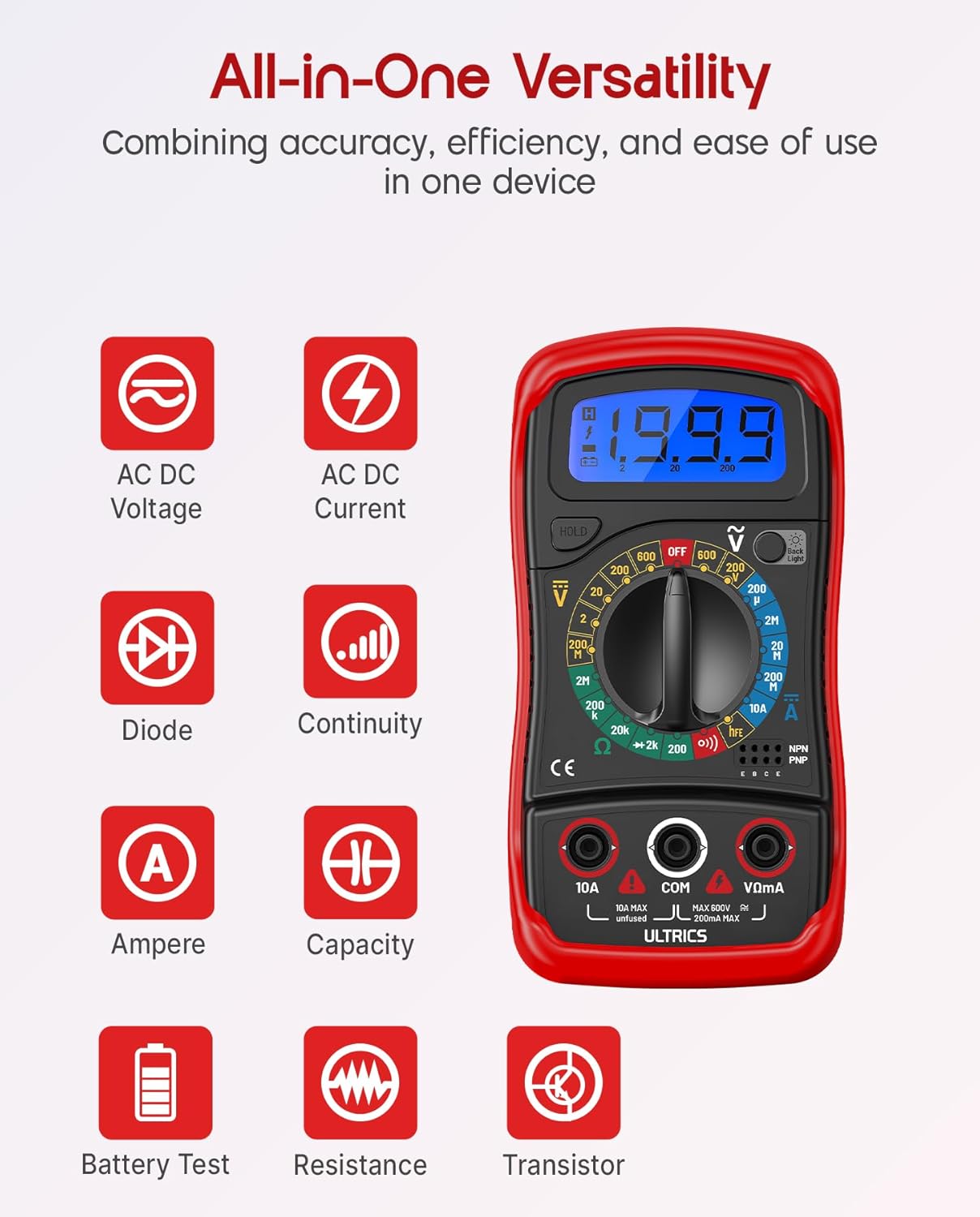
Image: Visual representation of the multimeter's versatile functions, including AC/DC Voltage, AC/DC Current, Diode, Continuity, Ampere, Capacity, Battery Test, Resistance, and Transistor measurements.
Pomiar objętości DCtage (prąd stały)
- Podłącz czarny przewód pomiarowy do KOM gniazdo i czerwony przewód pomiarowy do VΩmA podnośnik.
- Turn the function switch to the desired VDC range (e.g., 200mV, 2V, 20V, 200V, 600V). If unsure, start with the highest range and decrease as needed.
- Podłącz przewody pomiarowe równolegle do mierzonego elementu lub obwodu.
- Przeczytaj tomtage wartość na wyświetlaczu LCD.
Pomiar objętości ACtage (VAC)
- Podłącz czarny przewód pomiarowy do KOM gniazdo i czerwony przewód pomiarowy do VΩmA podnośnik.
- Turn the function switch to the desired ODKURZACZ range (e.g., 200V, 600V).
- Podłącz przewody pomiarowe równolegle do obwodu prądu przemiennegotagŹródło.
- Przeczytaj tomtage wartość na wyświetlaczu LCD.
Measuring DC Current (ADC)
OSTROŻNOŚĆ: Never connect the multimeter in parallel when measuring current. Always connect it in series with the circuit. Improper connection can damage the multimeter or the circuit.
- Wyłącz zasilanie obwodu.
- For currents up to 200mA, connect the black test lead to the KOM gniazdo i czerwony przewód pomiarowy do VΩmA podnośnik.
- For currents up to 10A, connect the black test lead to the KOM gniazdo i czerwony przewód pomiarowy do 10A podnośnik.
- Turn the function switch to the desired ADC range (e.g., 200µA, 2mA, 20mA, 200mA, 10A).
- Przerwij obwód i podłącz multimetr szeregowo do obwodu.
- Turn on power to the circuit.
- Odczytaj aktualną wartość na wyświetlaczu LCD.
- Turn off power to the circuit before disconnecting the multimeter.
Measuring Resistance (Ω)
OSTROŻNOŚĆ: Ensure the circuit is completely de-energized before measuring resistance. Measuring resistance on a live circuit can damage the multimeter.
- Podłącz czarny przewód pomiarowy do KOM gniazdo i czerwony przewód pomiarowy do VΩmA podnośnik.
- Turn the function switch to the desired Ω range (e.g., 200Ω, 2kΩ, 20kΩ, 200kΩ, 2MΩ, 20MΩ).
- Podłącz przewody pomiarowe do elementu, którego rezystancję chcesz zmierzyć.
- Odczytaj wartość rezystancji na wyświetlaczu LCD.
Test ciągłości
The continuity test checks for a complete circuit path. An audible buzzer will sound if continuity is detected.
- Podłącz czarny przewód pomiarowy do KOM gniazdo i czerwony przewód pomiarowy do VΩmA podnośnik.
- Przekręć przełącznik funkcji na Ciągłość (buzzer) position.
- Podłącz przewody pomiarowe do obwodu lub elementu.
- Jeżeli rezystancja jest mniejsza niż około 50Ω, rozlegnie się sygnał dźwiękowy wskazujący ciągłość.
Test Diody
Test diody mierzy głośność w przódtagspadek diody.
- Podłącz czarny przewód pomiarowy do KOM gniazdo i czerwony przewód pomiarowy do VΩmA podnośnik.
- Przekręć przełącznik funkcji na Dioda pozycja.
- Connect the red test lead to the anode (+) and the black test lead to the cathode (-) of the diode.
- Przeczytaj cztage drop on the LCD display. Reverse the leads; the display should show "OL" (Overload) for a good diode.
Test tranzystora hFE
This function tests the DC current gain (hFE) of NPN and PNP transistors.
- Przekręć przełącznik funkcji na hFE pozycja.
- Identify the Emitter (E), Base (B), and Collector (C) leads of the transistor.
- Insert the transistor leads into the corresponding holes in the hFE socket on the multimeter, ensuring correct NPN or PNP type.
- Odczytaj wartość hFE na wyświetlaczu LCD.
Funkcja zatrzymania danych
Naciśnij TRZYMAĆ Naciśnij przycisk, aby zamrozić aktualny odczyt na wyświetlaczu. Naciśnij go ponownie, aby zwolnić blokadę i wznowić odczyty na żywo.
Funkcja podświetlenia
Naciśnij Podświetlenie button to turn the LCD backlight on or off, improving visibility in dim environments.

Obraz: Zbliżenie view of the multimeter's LCD display, demonstrating its bright backlight feature for enhanced readability in various lighting conditions.
Konserwacja
Czyszczenie
Aby wyczyścić multimetr, przetrzyj obudowę miękką szmatką.amp cloth and a mild detergent. Do not use abrasives or solvents, as these may damage the casing lub wyświetlacz.
Wymiana baterii
When the low battery indicator appears on the display, replace the 9V battery as described in the "Installing the Battery" section to ensure continued accurate readings.
Wymiana bezpiecznika
If the current measurement function stops working, the fuse may need replacement. This multimeter is equipped with internal fuses for protection.
- Upewnij się, że multimetr jest WYŁĄCZONY i wszystkie przewody pomiarowe są odłączone.
- Zdejmij pokrywę baterii i wyjmij baterię.
- Carefully open the main casing (this may require removing additional screws, typically located under the rubber shell).
- Locate the fuse(s) on the circuit board. This model typically uses a 200mA/250V fuse for the mA range and a 10A/250V fuse for the 10A range.
- Replace the blown fuse with a fuse of the same type and rating. Never use a fuse with a different rating.
- Reassemble the multimeter, ensuring all screws are tightened and the casing is properly sealed.
Składowanie
If the multimeter is not used for a long period, remove the battery to prevent leakage and store the device in a cool, dry place, away from direct sunlight and extreme temperatures.
Rozwiązywanie problemów
| Problem | Możliwa przyczyna | Rozwiązanie |
|---|---|---|
| Brak wyświetlacza lub wyświetlacz jest przyciemniony | Rozładowana lub słaba bateria | Wymień baterię 9V. |
| Wyświetlany jest komunikat „OL” (Przeciążenie) | Input value exceeds selected range; open circuit (for resistance/continuity) | Select a higher range; check for breaks in the circuit or component. |
| Błędne odczyty | Wybrano nieprawidłową funkcję/zakres; słabe połączenie przewodów pomiarowych; niski poziom naładowania baterii | Verify function switch position and range; ensure leads are firmly connected; replace battery. |
| Pomiar prądu nie działa | Przepalony bezpiecznik | Wymień odpowiedni bezpiecznik (patrz rozdział Konserwacja). |
| Brak brzęczyka ciągłości | Obwód otwarty; rezystancja zbyt wysoka | Ensure circuit is closed; check resistance value (buzzer typically activates below 50Ω). |
Specyfikacje
| Funkcja | Szczegół |
|---|---|
| Model | Digital Multimeter D2 |
| Wyświetlacz | 3 ½ digit LCD, 1999 counts, with backlight |
| Objętość DCtage | 200mV / 2V / 20V / 200V / 600V |
| AC Objętośćtage | 200V / 600V |
| Prąd stały | 200µA / 2mA / 20mA / 200mA / 10A |
| Opór | 200Ω / 2kΩ / 20kΩ / 200kΩ / 2MΩ / 20MΩ |
| Test Diody | Tak |
| Ciągły brzęczyk | Tak |
| Test tranzystora hFE | Tak |
| Wstrzymanie danych | Tak |
| Źródło zasilania | Bateria 9V |
| Ocena bezpieczeństwa | IEC CAT II 600V, CE, RoHS compliant |
| Wymiary (dł. x szer. x wys.) | 14.6 x 10 x 5 cm (5.75 x 3.94 x 1.97 cala) |
| Waga | 240 gramów (0.53 funta) |
Gwarancja i wsparcie
ULTRICS provides a 12-month warranty for this product, covering manufacturing defects from the date of purchase. Please retain your proof of purchase for warranty claims.
For technical support, warranty claims, or any questions regarding your ULTRICS Digital Multimeter D2, please contact ULTRICS customer service through the retailer's platform or the official ULTRICS webStrona. Kontaktując się z pomocą techniczną, przygotuj dane dotyczące zakupu i numer modelu.
Producent: ULTRY
Numer modelu: Digital Multimeter D2
ASIN: B0DYP62MW7


