1. Wprowadzenie
The ZOYI VC17B+ is a high-performance, True-RMS digital multimeter designed for accurate measurement of various electrical parameters. It features a large, backlit display for clear readings in diverse environments and a robust design suitable for electricians, students, and maintenance professionals. This manual provides essential information for the safe and effective operation of your device.
Kluczowe możliwości obejmują:
- AC/DC Objętośćtage i pomiar prądu
- Resistance, Capacitance, and Frequency measurement
- Continuity and Diode testing
- Pomiar temperatury
- Cykl pracy
- Additional functions: True-RMS, Data Hold, Backlight, Low Battery Alert, Auto Power Off, MAX/MIN, Relative Measurement (REL)
2. Informacje dotyczące bezpieczeństwa
Zawsze przestrzegaj środków ostrożności podczas korzystania z urządzeń do pomiaru napięcia elektrycznego. Nieprzestrzeganie ich może spowodować porażenie prądem, obrażenia ciała lub uszkodzenie miernika lub testowanego urządzenia.
- Przeczytaj dokładnie tę instrukcję przed operacją.
- The ZOYI VC17B+ is rated for CAT IV 600 V. I CAT III 600 V.. Do not exceed these voltagi limity.
- Przed każdym użyciem sprawdź przewody pomiarowe pod kątem uszkodzeń. W przypadku uszkodzenia izolacji wymień je.
- Do not use the meter if it appears damaged or is not operating correctly.
- Ensure the function dial is set to the correct range before making measurements.
- Unikaj pracy w pojedynkę.
- Zachowaj ostrożność podczas pracy z objętościątagNie należy używać urządzeń o napięciu powyżej 30 V AC RMS, 42 V szczytowym lub 60 V DC, ponieważ stwarzają one zagrożenie porażenia prądem.
- Wymień baterie niezwłocznie, gdy pojawi się wskaźnik niskiego poziomu naładowania baterii.
3. Zawartość opakowania
Sprawdź, czy w przesyłce znajdują się wszystkie elementy:
- ZOYI VC17B+ Digital Multimeter
- Przewody pomiarowe (2)
- Baterie AA (2)
- Thermocouple Probe (1)
- Instrukcja obsługi (ten dokument)
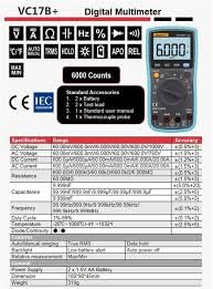
Figure 3.1: Standard Accessories included with the ZOYI VC17B+ Multimeter.
4. Koniec produktuview
Familiarize yourself with the components of the ZOYI VC17B+ multimeter:
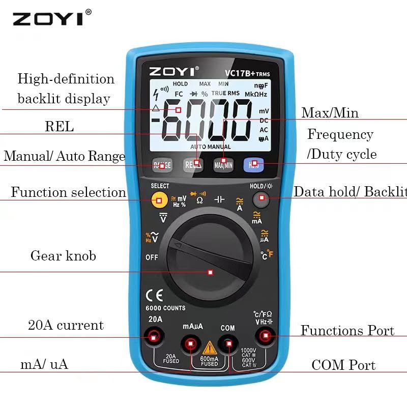
Figure 4.1: ZOYI VC17B+ Multimeter Components.
- Wyświetlacz: Large, high-definition backlit LCD for reading measurements.
- Function Dial (Gear Knob): Służy do wyboru żądanej funkcji pomiarowej.
- Gniazda wejściowe:
- KOM: Wspólny (ujemny) sygnał wejściowy dla wszystkich pomiarów.
- VHzΩ: Pozytywny wkład dla Voltage, Frequency, Resistance, Capacitance, Diode, Continuity, and Temperature measurements.
- mA/uA: Pozytywny sygnał wejściowy dla miliampere i mikroamppomiary prądu ere (połączone).
- 20A: Pozytywny sygnał wejściowy dla 20 Amppomiary prądu ere (połączone).
- Pikolak:
- ZASIĘG: Manual/Auto Range selection.
- REL: Funkcja pomiaru względnego.
- MAKS./MIN.: Rejestruje wartości maksymalne i minimalne.
- Hz%: Selects Frequency or Duty Cycle.
- HOLD/☀: Data Hold function and Backlight activation.
- WYBIERAĆ: Toggles between functions on a single dial position (e.g., AC/DC, Diode/Continuity).
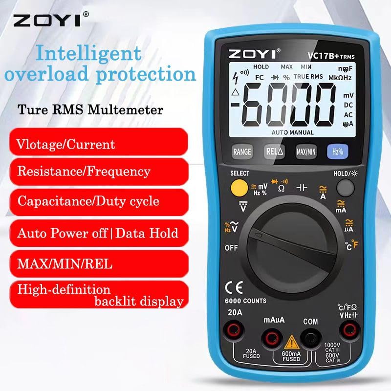
Figure 4.2: ZOYI VC17B+ Multimeter Front View.
5. Konfiguracja
5.1 Instalacja baterii
- Upewnij się, że multimetr jest wyłączony.
- Znajdź komorę baterii z tyłu miernika.
- Użyj śrubokręta, aby otworzyć pokrywę baterii.
- Insert two AA batteries, observing correct polarity (+/-).
- Załóż pokrywę baterii i zabezpiecz ją śrubą.
5.2 Podłączanie przewodów pomiarowych
Zawsze podłączaj czarny przewód pomiarowy do gniazda COM. Podłącz czerwony przewód pomiarowy do odpowiedniego gniazda wejściowego, w zależności od rodzaju pomiaru:
- VHzΩ: dla objtage, Resistance, Capacitance, Frequency, Diode, Continuity, and Temperature.
- mA/uA: For small current measurements.
- 20A: Do pomiarów dużych prądów (do 20A).
5.3 Korzystanie z podpórki
The multimeter includes a built-in kickstand for convenient hands-free operation. Gently pull out the kickstand from the back of the unit to prop it up at an angle. Push it back in when not needed.


Figure 5.1: Multimeter back view (left) and with kickstand deployed (right).
6. Instrukcja obsługi
6.1 Ogólne zasady działania
- Włączanie/wyłączanie zasilania: Rotate the function dial from 'OFF' to any measurement function to turn the meter ON. Rotate back to 'OFF' to power OFF.
- Automatyczne wyłączanie (APO): The meter will automatically power off after approximately 15 minutes of inactivity to conserve battery life. Press any button or rotate the function dial to wake it up.
- Podświetlenie: Press and hold the 'HOLD/☀' button to turn the backlight ON or OFF.
- Przechowywanie danych: Press the 'HOLD/☀' button briefly to freeze the current reading on the display. Press again to release.
- Zakres automatyczny/ręczny: The meter defaults to auto-ranging. Press the 'RANGE' button to switch to manual ranging. In manual ranging, press 'RANGE' repeatedly to cycle through available ranges. Press and hold 'RANGE' to return to auto-ranging.
- Przycisk WYBIERZ: In certain dial positions (e.g., Voltage, Diode/Continuity), press 'SELECT' to toggle between AC/DC, Diode Test, or Continuity Test.
6.2 Specyficzne funkcje pomiarowe
6.2.1 objtagPomiary (prąd przemienny/stały)
- Insert the black test lead into the COM jack and the red test lead into the VHzΩ jack.
- Obróć pokrętło funkcji na pozycję „V~” (objętość prądu przemiennego)tage) lub 'V=' (objętość DCtage) position. If both are on one position, use 'SELECT' to choose.
- Podłącz sondy pomiarowe równolegle do obwodu lub elementu, który chcesz zmierzyć.
- Przeczytaj tomtage wartość na wyświetlaczu.
6.2.2 Pomiar prądu (AC/DC)
OSTROŻNOŚĆ: Nigdy nie podłączaj miernika równolegle do miernika objętości.tagPodczas pomiaru prądu należy odłączyć źródło zasilania. Może to spowodować przepalenie bezpiecznika lub uszkodzenie miernika.
- Insert the black test lead into the COM jack.
- For mA/uA measurements, insert the red test lead into the mA/uA jack. For 20A measurements, insert the red test lead into the 20A jack.
- Rotate the function dial to the appropriate 'A~' (AC Current) or 'A=' (DC Current) position (mA, uA, or 20A). Use 'SELECT' if needed.
- Otwórz obwód i podłącz sondy pomiarowe szeregowo z obciążeniem.
- Odczytaj aktualną wartość na wyświetlaczu.
6.2.3 Pomiar rezystancji (Ω)
OSTROŻNOŚĆ: Przed pomiarem rezystancji należy upewnić się, że obwód jest odłączony od napięcia i wszystkie kondensatory są rozładowane.
- Insert the black test lead into the COM jack and the red test lead into the VHzΩ jack.
- Obróć pokrętło funkcji do pozycji „Ω”.
- Podłącz sondy pomiarowe do mierzonego elementu.
- Odczytaj wartość rezystancji z wyświetlacza.
6.2.4 Test ciągłości
- Insert the black test lead into the COM jack and the red test lead into the VHzΩ jack.
- Rotate the function dial to the 'Ω' position and press 'SELECT' until the continuity symbol (buzzer icon) is displayed.
- Podłącz sondy pomiarowe do obwodu lub elementu.
- If continuity exists (resistance below approx. 50Ω), the buzzer will sound.
6.2.5 Test diody
- Insert the black test lead into the COM jack and the red test lead into the VHzΩ jack.
- Rotate the function dial to the 'Ω' position and press 'SELECT' until the diode symbol (->|) is displayed.
- Podłącz czerwoną sondę do anody, a czarną do katody diody. Na wyświetlaczu pojawi się napięcie przewodzenia.tagkropla.
- Zamień miejscami sondy. Na wyświetlaczu powinien pojawić się komunikat „OL” (pętla otwarta), oznaczający, że dioda jest sprawna.
6.2.6 Pomiar pojemności (F)
OSTROŻNOŚĆ: Discharge capacitors completely before testing to prevent damage to the meter.
- Insert the black test lead into the COM jack and the red test lead into the VHzΩ jack.
- Rotate the function dial to the 'F' (Capacitance) position.
- Podłącz sondy testowe do kondensatora.
- Odczytaj wartość pojemności na wyświetlaczu.
6.2.7 Frequency Measurement (Hz) and Duty Cycle (%)
- Insert the black test lead into the COM jack and the red test lead into the VHzΩ jack.
- Obróć pokrętło funkcji do pozycji 'Hz%'.
- Press the 'Hz%' button to toggle between Frequency (Hz) and Duty Cycle (%).
- Podłącz sondy pomiarowe równolegle do źródła sygnału.
- Odczytaj wartość częstotliwości lub współczynnika wypełnienia na wyświetlaczu.
6.2.8 Pomiar temperatury (°C/°F)
- Insert the thermocouple probe into the VHzΩ (positive) and COM (negative) jacks, observing polarity.
- Rotate the function dial to the '°C/°F' position.
- The display will show the ambient temperature. Place the thermocouple tip on or near the object whose temperature is to be measured.
- Read the temperature value. The unit can be toggled between Celsius and Fahrenheit using the 'SELECT' button if available in this mode.
6.2.9 Funkcja MAX/MIN
In any measurement mode, press the 'MAX/MIN' button to activate this function. The meter will display the maximum or minimum reading recorded since the function was activated. Press again to cycle between MAX, MIN, and current reading. Press and hold to exit.
6.2.10 REL (Relative Measurement) Function
Press the 'REL' button to store the current reading as a reference value. Subsequent measurements will be displayed as the difference from this reference value. Press 'REL' again to exit this mode.
7. Konserwacja
7.1 Czyszczenie
Wytrzyj licznik reklamąamp Ściereczką i łagodnym detergentem. Nie używaj środków ściernych ani rozpuszczalników. Przed użyciem upewnij się, że miernik jest całkowicie suchy.
7.2 Wymiana baterii
When the low battery indicator appears on the display, replace the batteries as described in Section 5.1. Use two new AA batteries.
7.3 Wymiana bezpiecznika
Jeśli funkcja pomiaru prądu nie działa, bezpiecznik może wymagać wymiany. Sprawdź specyfikację, aby uzyskać informacje o prawidłowym typie i parametrach bezpiecznika. Wymianę bezpiecznika powinien wykonywać wyłącznie wykwalifikowany personel.
7.4 Przechowywanie
Jeśli miernik nie będzie używany przez dłuższy czas, wyjmij baterie, aby zapobiec wyciekowi. Przechowuj miernik w chłodnym, suchym miejscu, z dala od bezpośredniego światła słonecznego i ekstremalnych temperatur.
8. Rozwiązywanie Problemów
| Problem | Możliwa przyczyna | Rozwiązanie |
|---|---|---|
| Brak wyświetlacza lub wyświetlacz jest przyciemniony | Baterie rozładowane lub słabe; Nieprawidłowa instalacja baterii. | Wymień baterie. Sprawdź biegunowość baterii. |
| Brak pomiaru prądu | Blown fuse; Incorrect input jack used. | Replace fuse (if qualified); Ensure red lead is in mA/uA or 20A jack. |
| Wyświetlany jest komunikat „OL” (Przeciążenie) | Pomiar przekracza wybrany zakres lub maksymalną pojemność miernika. | Switch to a higher range (if in manual mode); Ensure measurement is within meter's limits. |
| Niedokładne odczyty | Poor test lead connection; External interference; Damaged meter. | Check connections; Move away from strong electromagnetic fields; Contact support if meter is damaged. |
9. Specyfikacje
Detailed technical specifications for the ZOYI VC17B+ Digital Multimeter:
9.1 Specyfikacje ogólne
- Marka: ZOYI
- Numer modelu: VC17B+
- Wyświetlacz: 6000 Counts, Large Backlit LCD
- Prawdziwy RMS: Tak
- Źródło zasilania: 2 baterie AA
- Ocena bezpieczeństwa: KAT IV 600 V, KAT III 600 V
- Wymiary (dł. x szer. x wys.): 180 x 90 x 45 mm (około)
- Waga: Około 310g (bez baterii)
- Automatyczne wyłączanie: Tak
- Przechowywanie danych: Tak
- Alert niskiego poziomu baterii: Tak

Rysunek 9.1: Wymiary fizyczne multimetru.
9.2 Specyfikacje elektryczne
Rysunek 9.2: Szczegółowe specyfikacje elektryczne.
| Funkcjonować | Zakres | Dokładność |
|---|---|---|
| Objętość DCtage | 60.00mV/600.0mV/6.000V/60.00V/600.0V/1000V | ±(0.5%+3) |
| AC Objętośćtage | 60.00mV/600.0mV/6.000V/60.00V/600.0V/750V | ±(1.0%+3) |
| Prąd stały | 600.0uA/6000uA/60.00mA/600.0mA/6.000A/20.00A | ±(1.2%+3) |
| Prąd zmienny | 600.0uA/6000uA/60.00mA/600.0mA/6.000A/20.00A | ±(1.5%+3) |
| Opór | 600.0Ω/6.000kΩ/60.00kΩ/600.0kΩ/6.000MΩ/60.00MΩ | ±(1.0%+3) |
| Pojemność | 9.999nF/99.99nF/999.9nF/9.999uF/99.99uF/999.9uF/9.999mF | ±(5.0%+20) |
| Częstotliwość | 9.999Hz/99.99Hz/999.9Hz/9.999kHz/99.99kHz/999.9kHz/9.999MHz | ±(0.1%+2) |
| Temperatura | -20°C ~ 1000°C / -4°F ~ 1832°F | ±(2.5%+5) |
| Dioda/Ciągłość | Tak | Tak |
10. Gwarancja i wsparcie
For warranty information, please refer to the warranty card included with your product or visit the official ZOYI website. For technical support or service inquiries, please contact your retailer or the manufacturer directly.
- Producent: ZOYI & ZOTEK Instruments
- Packer Contact Information: Skyking Instruments, Mumbai, INDIA