1. Wprowadzenie
This manual provides essential information for the safe and effective installation, operation, and maintenance of the XIBANY GV2-PM21C Three-Phase Motor Circuit Breaker. Please read this manual thoroughly before attempting any installation or operation to ensure proper function and safety.
The GV2-PM21C is designed to protect three-phase motors against overloads, short circuits, and phase failures. It features a thermal-magnetic trip unit and a rotary knob for control.
2. Informacje dotyczące bezpieczeństwa
OSTRZEŻENIE: Niebezpieczeństwo porażenia prądem elektrycznym. Montaż i konserwację powinien wykonywać wyłącznie wykwalifikowany personel.
- Always disconnect power before working on the circuit breaker or connected equipment.
- Należy zapewnić prawidłowe uziemienie wszystkich podzespołów elektrycznych.
- Verify that the circuit breaker's ratings match the motor and supply specifications.
- Do not operate the circuit breaker if it appears damaged.
- Należy przestrzegać wszystkich lokalnych i krajowych przepisów i regulacji dotyczących instalacji elektrycznych.
3. Koniec produktuview
The XIBANY GV2-PM21C is a compact motor circuit breaker designed for industrial applications. Key features include a rotary operating handle, thermal and magnetic trip indicators, and clearly marked terminals.

Rycina 3.1: Przód View of GV2-PM21C. This image displays the front of the motor circuit breaker, showing the rotary knob for operation, the 'TRIP' indicator, the 'TEST' button, and the main power terminals (1L1, 3L2, 5L3 at the top; 2T1, 4T2, 6T3 at the bottom).

Rysunek 3.2: Kątowy View ze specyfikacjami. Ten view shows the circuit breaker from an angle, highlighting the side label which contains detailed technical specifications such as rated voltage, current range, breaking capacity, and compliance standards.

Rysunek 3.3: Strona View. This image provides a side perspective of the circuit breaker, illustrating its compact design and potential mounting features.
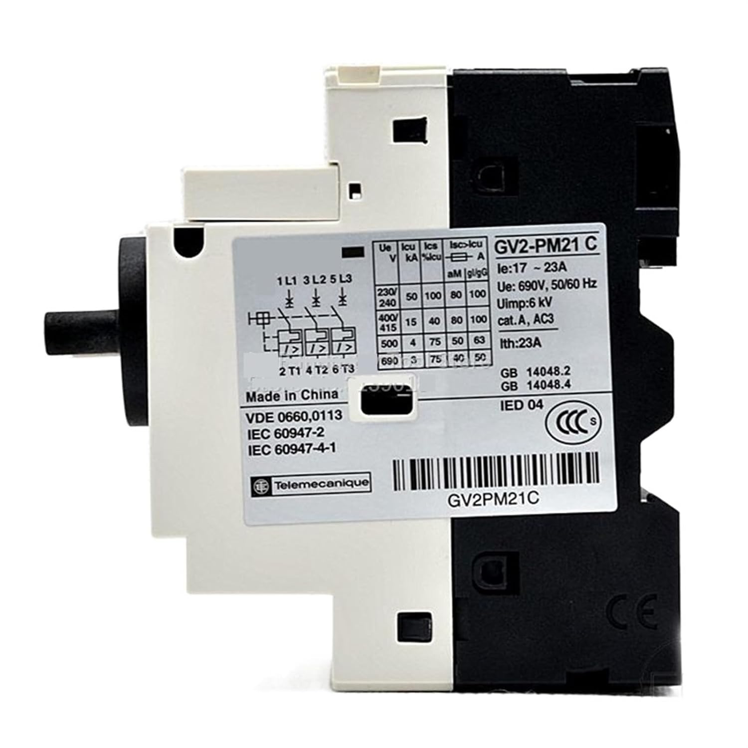
Figure 3.4: Detailed Technical Label. A close-up of the technical label on the side of the breaker, clearly showing the electrical ratings, such as the current adjustment range (Ie: 17-23A), rated operational voltage (Ue: 690V, 50/60Hz), impulse withstand voltage (Uimp: 6kV), and various breaking capacities (Ics, Icu) at different voltagt.j.
4. Specyfikacje
| Parametr | Wartość |
|---|---|
| Model | GV2-PM21C |
| Current Adjustment Range (Ie) | 17 - 23 A |
| Znamionowa objętość operacyjnatage (Ue) | 690VAC, 50/60Hz |
| Znamionowa wytrzymałość na impuls Voltage (Uimp) | 6kV |
| Prąd cieplny znamionowy (Ith) | 23 A |
| Polacy | 3P |
| Typ | Typ gałki |
| Zgodność ze standardami | VDE 0660.0113, IEC 60947-2, IEC 60947-4-1, GB 14048.2, GB 14048.4 |
| Producent | XIBANY |
5. Konfiguracja i instalacja
Instalację musi wykonać wykwalifikowany elektryk, zgodnie ze wszystkimi obowiązującymi normami i przepisami elektrycznymi.
5.1 Montaż
- Ensure the mounting surface is stable and free from vibrations.
- Mount the circuit breaker vertically on a DIN rail or using screws through the designated mounting holes.
- Allow adequate clearance around the breaker for ventilation and wiring.
5.2 Okablowanie
- Odłącz wszystkie źródła zasilania before beginning wiring.
- Connect the incoming three-phase power supply to terminals 1L1, 3L2, and 5L3.
- Connect the motor load to terminals 2T1, 4T2, and 6T3.
- Sprawdź, czy wszystkie połączenia są dobrze dokręcone i bezpieczne, aby zapobiec poluzowaniu się styków i przegrzaniu.
- Verify correct phase sequence if required by the motor.
5.3 Ustawienia bieżące
- Adjust the thermal trip setting (current adjustment knob) to match the motor's full load current (FLC). The range is 17-23A.
- Refer to the motor's nameplate for its FLC.
6. Instrukcja obsługi
6.1 Włączanie/wyłączanie
- Włączyć: Rotate the operating knob clockwise to the "I" (ON) position.
- Wyłączyć: Rotate the operating knob counter-clockwise to the "O" (OFF) position.
6.2 Trip Indication and Reset
- If an overload or short circuit occurs, the breaker will trip, and the "TRIP" indicator will become visible. The knob will move to an intermediate position.
- Aby zresetować: First, rotate the knob fully counter-clockwise to the "O" (OFF) position. Then, rotate it clockwise to the "I" (ON) position.
- Before resetting, identify and rectify the cause of the trip.
6.3 Funkcja testowa
- The "TEST" button allows for manual verification of the tripping mechanism.
- Press the "TEST" button to simulate an overload trip. The breaker should trip, and the "TRIP" indicator should appear.
- Reset the breaker after testing as described above.
7. Konserwacja
Regular maintenance helps ensure the longevity and reliable operation of the circuit breaker.
- Przeglądy okresowe: Visually inspect the breaker for any signs of damage, discoloration, or loose connections.
- Czyszczenie: Keep the breaker clean and free from dust and debris. Use a dry, lint-free cloth. Do not use solvents or abrasive cleaners.
- Kontrola połączenia: Periodically check terminal screws for tightness.
- Test funkcjonalny: Perform the "TEST" function periodically (e.g., annually) to ensure the tripping mechanism is operational.
8. Rozwiązywanie Problemów
| Problem | Możliwa przyczyna | Rozwiązanie |
|---|---|---|
| Częste wyzwalanie wyłączników | Overload, short circuit, phase imbalance, motor fault, incorrect current setting. | Check motor load, inspect wiring for short circuits, verify motor health, adjust current setting to motor FLC. |
| Breaker does not reset | Persistent fault, internal damage. | Ensure the fault is cleared. If the fault persists or the breaker is damaged, replace the unit. |
| Silnik nie uruchamia się | Breaker in OFF or TRIP position, no power supply, wiring error. | Check breaker position, verify power supply, inspect wiring connections. |
If troubleshooting steps do not resolve the issue, contact qualified technical support.
9. Informacje o gwarancji
Warranty terms and conditions for the XIBANY GV2-PM21C Motor Circuit Breaker are provided by the seller or manufacturer at the time of purchase. Please retain your proof of purchase for warranty claims. For specific details, refer to the documentation included with your product or contact your point of purchase.
10. Wsparcie techniczne
For technical assistance, questions regarding installation, operation, or troubleshooting that are not covered in this manual, please contact the seller or XIBANY customer support. Have your product model number (GV2-PM21C) and purchase information ready when contacting support.
You may also refer to the manufacturer's official website for additional resources or updated documentation.


