1. Wprowadzenie
The FlySky FTr12B is a high-performance 12-channel receiver designed for remote control applications, including drones and fixed-wing aircraft. It utilizes the advanced AFHDS 3 (3rd Generation) protocol, offering reliable 2-way communication and enhanced signal stability through its dual antenna system. This receiver provides versatile output options including PWM, PPM, i.Bus, and S.Bus, ensuring compatibility with a wide range of flight controllers and servos.
This manual provides essential information for the proper setup, operation, and maintenance of your FTr12B receiver.
2. Specyfikacje
| Model produktu: | FTR12B |
| Kanały PWM: | 12 |
| Częstotliwość bezprzewodowa: | 2.4 GHz |
| Protokół bezprzewodowy: | AFHDS3 |
| Typ anteny: | Podwójna antena |
| Zasilanie: | 3.5-9 V |
| RSSI: | Utrzymany |
| Interfejs danych: | PWM/PPM /i.Bus/S.Bus |
| Zakres temperatur: | -10°C do +60°C |
| Zakres wilgotności: | 20%-95% |
| Aktualizacja online: | Utrzymany |
| Wymiary: | Wymiary: 39 x 32 x 15 mm |
| Masa ciała: | 15 gramów |
| Orzecznictwo: | CE, FCC ID: N4ZFTR12B00 |
3. Konfiguracja
3.1 Odbiornik ponadview
Familiarize yourself with the receiver's components and ports.
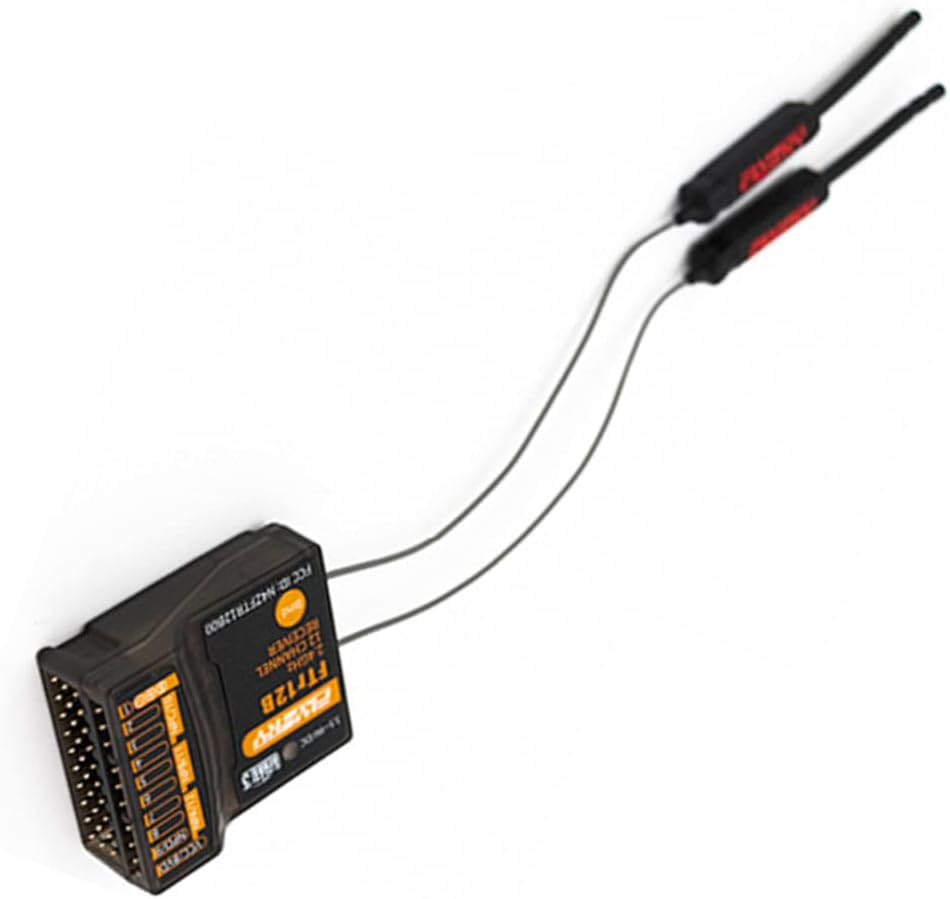
Rysunek 1: Z góry na dół view of the FTr12B receiver, showing the main unit and its two external antennas. The antennas are connected via thin wires and are designed for optimal signal reception.
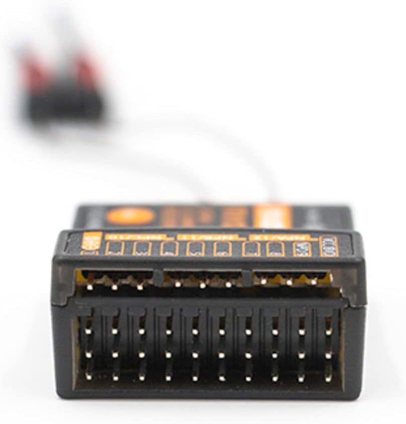
Rysunek 2: Close-up of the FTr12B receiver's multiple port pins, used for connecting servos, flight controllers, and power. These ports support various output protocols including PWM, PPM, i.Bus, and S.Bus.
3.2 Procedura wiązania
To establish communication between your FTr12B receiver and a compatible FlySky transmitter (AFHDS 3 protocol), follow these steps:
- Upewnij się, że nadajnik jest wyłączony.
- Connect the binding plug (not included, typically a jumper wire) to the BIND port on the FTr12B receiver.
- Apply power to the receiver (3.5-9V). The receiver's LED indicator should flash rapidly, indicating it is in binding mode.
- Power on your FlySky AFHDS 3 compatible transmitter and navigate to the binding menu.
- Rozpocznij proces wiązania w nadajniku.
- Po pomyślnym nawiązaniu połączenia dioda LED odbiornika zacznie świecić światłem ciągłym.
- Disconnect power from the receiver, remove the binding plug, and then reconnect power. The receiver should now be bound to your transmitter.
Notatka: Refer to your specific FlySky transmitter's manual for detailed binding instructions, as procedures may vary slightly.
3.3 Umiejscowienie anteny
Proper antenna placement is crucial for optimal signal reception and range. The FTr12B features dual antennas. Follow these guidelines:
- Mount the antennas at a 90-degree angle to each other to ensure diverse signal reception regardless of aircraft orientation.
- Keep antennas away from carbon fiber, metal parts, motors, ESCs, and other electronic components that can shield or interfere with the signal.
- Ensure the active part of the antenna (the last 31mm of the coaxial cable, without the outer insulation) is exposed and not bent sharply.
- Secure the antennas firmly to prevent movement during flight, using antenna tubes or appropriate mounting solutions.

Rysunek 3: The FTr12B receiver with its dual antennas. Proper orientation and separation of these antennas are vital for maintaining a strong and reliable radio link.
3.4 Output Configuration (PWM/PPM/i.Bus/S.Bus)
The FTr12B supports multiple output protocols. The specific configuration method depends on your flight controller and transmitter settings. Generally, the output mode is selected via the transmitter's system menu or automatically detected by the flight controller.
- PWM (modulacja szerokości impulsu): Each channel has a dedicated pin. Connect servos or ESCs directly to the corresponding PWM pins.
- PPM (Pulse Position Modulation): All channels are multiplexed onto a single pin. Connect the PPM output pin to your flight controller's PPM input.
- i.Bus / S.Bus: These are serial bus protocols that transmit all channel data over a single wire, often with telemetry. Connect the i.Bus or S.Bus output pin to your flight controller's serial input.
Consult your flight controller's manual for specific wiring and configuration details for each protocol.
4. Instrukcja obsługi
4.1 Włączanie i wstępne sprawdzenie
- Sprawdź, czy wszystkie połączenia są bezpieczne i prawidłowe.
- Najpierw włącz nadajnik.
- Apply power to the FTr12B receiver. The receiver's LED should illuminate solid, indicating a successful link with the transmitter.
- Verify that all control surfaces and functions respond correctly to transmitter inputs.
4.2 RSSI (Received Signal Strength Indication)
The FTr12B supports RSSI output, which provides real-time information about the signal strength between the transmitter and receiver. This data can be displayed on your transmitter or OSD (On-Screen Display) if your flight controller supports it. Monitoring RSSI is crucial for understanding your radio link quality and preventing flights beyond safe range.
4.3 Ustawienia bezpieczeństwa
Failsafe is a critical safety feature that defines the receiver's behavior in case of signal loss. It is highly recommended to configure failsafe settings on your transmitter. Common failsafe options include:
- Trzymać: The receiver holds the last received command. (Not recommended for most aircraft).
- Brak pulsu: The receiver stops sending pulses to all channels.
- Zwyczaj: Pre-set specific positions for each channel (e.g., throttle to zero, control surfaces neutral or slightly up for glide). This is the most recommended option for safety.
Always test your failsafe settings on the ground before flight to ensure they function as intended.
5. Konserwacja
5.1 Czyszczenie i przechowywanie
- Utrzymuj odbiornik w czystości, chroniąc go przed kurzem, brudem i wilgocią. Do czyszczenia używaj miękkiej, suchej ściereczki.
- Unikaj wystawiania odbiornika na działanie ekstremalnych temperatur lub bezpośredniego światła słonecznego przez dłuższy czas.
- Store the receiver in a dry, cool environment when not in use.
5.2 aktualizacji oprogramowania sprzętowego
The FTr12B receiver supports online firmware updates. Regularly check the official FlySky website for the latest firmware versions. Firmware updates can improve performance, add new features, or fix bugs. Follow the instructions provided with the firmware update utility carefully to avoid damaging the receiver.
Ensure a stable power supply during the update process. Interrupting the update can render the receiver inoperable.
6. Rozwiązywanie Problemów
6.1 Brak sygnału / Dioda LED odbiornika nie świeci światłem ciągłym
- Sprawdź powiązanie: Ensure the receiver is correctly bound to your transmitter. Repeat the binding procedure if necessary.
- Nadajnik włączony: Verify that your transmitter is powered on and operating on the correct model memory.
- Zasilanie: Confirm the receiver is receiving adequate power (3.5-9V). Check wiring and battery connections.
- Połączenie antenowe: Ensure antennas are securely connected to the receiver and not damaged.
- Zakres: Move the transmitter closer to the receiver to rule out range issues.
6.2 Intermittent Signal / Glitches
- Umiejscowienie anteny: Re-evaluate antenna placement. Ensure they are clear of obstructions and mounted at 90 degrees to each other.
- Ingerencja: Check for potential sources of electrical interference near the receiver (e.g., motors, ESCs, video transmitters, high-current wires). Try to separate these components.
- Uszkodzone anteny: Inspect antennas for any cuts, kinks, or damage to the active element. Replace if damaged.
- Wahania mocy: Ensure the power supply to the receiver is stable and free from voltagkrople e.
6.3 Incorrect Channel Response
- Ustawienia nadajnika: Sprawdź przydział kanałów i ustawienia miksowania w swoim nadajniku.
- Konfiguracja kontrolera lotu: If using a flight controller, check its input mapping and calibration settings.
- Okablowanie: Double-check that servos/ESCs are connected to the correct output pins on the receiver or flight controller.
7. Wsparcie
For further assistance, technical support, or to download the latest firmware and manuals, please visit the official FlySky webstronie lub skontaktuj się z działem obsługi klienta.
Always refer to the most current documentation available from the manufacturer for the most accurate and up-to-date information.


