1. Wprowadzenie
This manual provides comprehensive instructions for the installation, operation, and maintenance of your AZZA CSAZ-340F CELESTA ATX Mid Tower Gaming Case. Please read this manual thoroughly before beginning installation to ensure proper setup and to maximize the performance and longevity of your system components.

Rysunek 1: The AZZA CSAZ-340F CELESTA Mid Tower ATX Case, showcasinze względu na jego konstrukcję i kształt.
2. Informacje dotyczące bezpieczeństwa
- Always disconnect the power supply from the wall outlet before installing or removing any components inside the case.
- Handle all components with care to prevent damage from electrostatic discharge (ESD). Consider using an anti-static wrist strap.
- Keep the case and components away from liquids and excessive moisture.
- Aby zapobiec przegrzaniu, należy zapewnić odpowiednią wentylację wokół obudowy.
- Do not attempt to modify the case structure or components, as this may void your warranty and pose safety risks.
- Przechowuj małe części i materiały opakowaniowe poza zasięgiem dzieci.
3. Zawartość opakowania
Sprawdź, czy w przesyłce znajdują się wszystkie wymienione poniżej elementy:
- AZZA CSAZ-340F CELESTA ATX Mid Tower Gaming Case
- Pudełko z akcesoriami (zawiera śruby, dystanse, opaski kablowe itp.)
- Instrukcja obsługi (ten dokument)
4. Specyfikacje
The following table details the technical specifications of the AZZA CSAZ-340F CELESTA case:
| Funkcja | Specyfikacja |
|---|---|
| Marka | AZZA |
| Nazwa modelu | CSAZ-340F CELESTA |
| Typ sprawy | Mid Tower |
| Zgodność płyty głównej | ATX, Micro ATX, Mini ITX |
| Kolor | Czarny |
| Tworzywo | Metal |
| Typ montażu zasilacza | Mocowanie dolne |
| Metoda chłodzenia | Powietrze |
| Fan Size (Included/Supported) | 120mm (Rear included), Supports 120mm/140mm |
| Maksymalna długość GPU | 320mm |
| Maksymalna wysokość chłodnicy procesora | 165mm |
| Maksymalna długość zasilacza | 160mm |
| 3.5" HDD Support | 2 |
| 2.5" SSD Support | 4/6 (depending on configuration) |
| Obsługa przedniego wentylatora | 3 x 120 mm lub 3 x 140 mm |
| Top Fan Support | 2 x 120 mm lub 2 x 140 mm |
| Wspornik wentylatora tylnego | 1 x 120mm |
| Przedni wspornik chłodnicy | Up to 280mm/360mm |
| Najlepsze wsparcie chłodnicy | 2 x 120mm (from image) |
| Wspornik tylnej chłodnicy | 1 x 120mm (from image) |
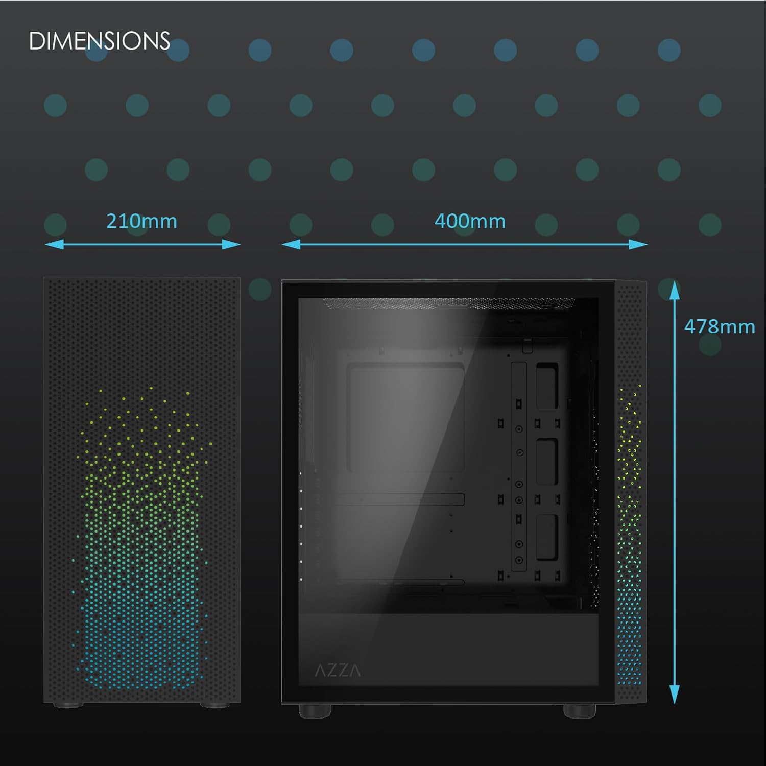
Rysunek 2: Physical dimensions of the AZZA CSAZ-340F CELESTA case: 210mm (width), 400mm (depth), 478mm (height).

Rysunek 3: Diagram illustrating fan and radiator mounting options for the AZZA CSAZ-340F CELESTA case, including front, top, and rear configurations.

Rysunek 4: Internal component support diagram for the AZZA CSAZ-340F CELESTA, showing maximum dimensions for CPU cooler, GPU, and PSU, along with drive bay locations.
5. Konfiguracja i instalacja
Follow these steps to install your components into the AZZA CSAZ-340F CELESTA case.
5.1 Przygotowanie sprawy
- Połóż obudowę na płaskiej i stabilnej powierzchni.
- Remove the side panels. Typically, these are secured with thumbscrews at the rear of the case.
5.2 Instalacja płyty głównej
- Install the I/O shield (if not pre-installed) into the rear opening of the case.
- Ensure the correct standoffs are installed for your ATX, Micro-ATX, or Mini-ITX motherboard. Adjust or add standoffs as needed using the provided tools.
- Ostrożnie umieść płytę główną na dystansach, dopasowując otwory na śruby.
- Secure the motherboard with the appropriate screws from the accessory box. Do not overtighten.
5.3 Instalacja zasilacza (PSU).
- Position the PSU in the bottom rear compartment of the case, ensuring the fan faces downwards (if there's a filtered vent) or upwards.
- Secure the PSU to the case with the provided screws from the rear.
- Route the necessary power cables through the cable management cutouts.
5.4 Instalacja dysku pamięci masowej (HDD/SSD)
- Dyski twarde 3.5": Locate the drive cage. Slide the 3.5" HDDs into the drive trays and secure them, often tool-less or with screws.
- Dyski SSD 2.5": Mount 2.5" SSDs to the dedicated mounting points on the motherboard tray or drive cage using screws.
- Connect SATA data and power cables to the installed drives.
5.5 Instalacja karty graficznej (GPU)
- Zdejmij niezbędne osłony gniazd PCIe z tyłu obudowy.
- Carefully insert your graphics card into the appropriate PCIe slot on the motherboard until it clicks into place.
- Przymocuj kartę graficzną do obudowy za pomocą śrub.
- Connect any required PCIe power cables from the PSU to the graphics card.
5.6 Montaż chłodnicy procesora
Install your CPU cooler according to its specific manufacturer instructions. Ensure it does not exceed the maximum height of 165mm.
5.7 Montaż wentylatora i chłodnicy
Obudowa obsługuje różne konfiguracje wentylatorów i radiatorów:
- Przód: Up to 3 x 120mm or 3 x 140mm fans, or radiators up to 280mm/360mm.
- Szczyt: Up to 2 x 120mm or 2 x 140mm fans, or 2 x 120mm radiators.
- Tył: 1 x 120mm fan (pre-installed) or 1 x 120mm radiator.
Mount fans and radiators using the appropriate screws and ensure proper airflow direction.
5.8 Zarządzanie kablami
Wykorzystaj wycięcia na kable i punkty mocowania za tacką płyty głównej, aby poprowadzić i zabezpieczyć kable. Poprawia to przepływ powietrza i estetykę.
5.9 Montaż końcowy
- Double-check all connections and ensure no cables are obstructing fans.
- Reattach the side panels.
- Connect external peripherals (monitor, keyboard, mouse, etc.) and the power cable.
6. Obsługa systemu
Once all components are installed and connected, you can power on your system. The front panel features power and reset buttons, along with USB and audio ports for convenient access.

Rysunek 5: Close-up of the AZZA CSAZ-340F CELESTA's front panel, highlighting the integrated lighting effects.
7. Konserwacja
- Filtry przeciwpyłowe: Regularly clean the dust filters (if present) to maintain optimal airflow and cooling performance.
- Czyszczenie wnętrza: Periodically open the case and use compressed air to remove dust from components and fans. Ensure the system is powered off and unplugged before cleaning.
- Czyszczenie zewnętrzne: Przetrzyj zewnętrzne powierzchnie miękką, damp płótno. Unikaj ostrych środków chemicznych.
8. Rozwiązywanie Problemów
Jeśli napotkasz problemy, rozważ poniższe typowe kroki rozwiązywania problemów:
- System się nie włącza:
- Upewnij się, że kabel zasilający jest solidnie podłączony do zasilacza i gniazdka ściennego.
- Check that the PSU switch is in the "ON" position.
- Verify all internal power connections (24-pin ATX, 8-pin CPU, PCIe power) are seated correctly.
- Confirm front panel power button cables are correctly connected to the motherboard.
- Brak wyjścia wyświetlacza:
- Ensure your monitor is connected to the graphics card (not the motherboard's integrated graphics ports, unless you are using integrated graphics).
- Ponownie włóż kartę graficzną do gniazda PCIe.
- Sprawdź wybór wejścia monitora.
- Przegrzanie:
- Verify all case fans are spinning and oriented correctly for airflow.
- Clean any dust filters and internal components.
- Ensure CPU cooler is properly seated and making good contact with the CPU.
9. Gwarancja i wsparcie
Aby uzyskać informacje o gwarancji i pomocy technicznej, zapoznaj się z oficjalną stroną AZZA webOdwiedź witrynę lub skontaktuj się bezpośrednio z obsługą klienta AZZA. Zachowaj dowód zakupu na wypadek roszczeń gwarancyjnych.
Oficjalny AZZA Webstrona: www.azza.com


