1. Wprowadzenie
This manual provides comprehensive instructions for the installation, operation, and maintenance of the HPE Aruba 8320 L3 managed switch. It is designed to assist users in understanding the product's features and ensuring its proper and safe use. Please read this manual thoroughly before operating the device.
2. Informacje dotyczące bezpieczeństwa
Aby zapobiec obrażeniom ciała i uszkodzeniom sprzętu, należy przestrzegać następujących środków ostrożności:
- Zapewnij prawidłowe uziemienie urządzenia.
- Do not operate the switch in environments with excessive heat, humidity, or dust.
- Use only the power supplies provided or specified by the manufacturer.
- Disconnect all power before performing any maintenance or installation procedures.
- Instalację i serwisowanie powinien wykonywać wyłącznie wykwalifikowany personel.
3. Zawartość opakowania
Sprawdź, czy w opakowaniu znajdują się wszystkie elementy:
- HPE Aruba 8320 Switch (32 x 40 Gigabit QSFP+ ports)
- 5 x Fan Modules
- 2 x Power Supply Units
- 2-post Rack Mounting Kit
- Power Cords (region specific)
- Kabel konsoli
4. Opis fizyczny
The HPE Aruba 8320 switch is a rack-mountable unit designed for high-density network environments. Its front panel features 32 QSFP+ ports for high-speed connectivity, along with management ports and status indicators.
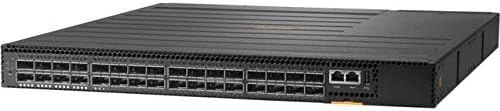
Rysunek 1: Przód view of the HPE Aruba 8320 Switch. The front panel displays 32 QSFP+ ports arranged in two rows, providing high-density 40 Gigabit connectivity. To the right, there are two RJ-45 management ports (console and out-of-band management) and status indicator LEDs for power, system, and port activity. The overall chassis is black with ventilation grilles on the top surface.
5. Konfiguracja i instalacja
5.1 Montaż w stojaku
The HPE Aruba 8320 switch is designed for installation in a standard 19-inch equipment rack using the provided 2-post rack mounting kit.
- Attach the rack ears to the sides of the switch using the supplied screws.
- Secure the switch into the rack using appropriate rack screws. Ensure the switch is level and adequately supported.
5.2 Połączenie zasilania
The switch is equipped with two hot-swappable power supply units for redundancy.
- Insert the power supply units into their respective bays at the rear of the switch.
- Connect the power cords to the power supply units and then to a grounded AC power source.
- Verify that the power supply LEDs illuminate, indicating proper power input.
5.3 Połączenia sieciowe
Connect network cables to the QSFP+ ports as required for your network topology. Use appropriate transceivers and fiber optic cables for 40 Gigabit connections.
5.4 Dostęp do konfiguracji początkowej
For initial configuration, connect a console cable from your management workstation to the console port on the switch. Alternatively, use the out-of-band management Ethernet port for network-based access after basic IP configuration.
6. Obsługa przełącznika
6.1 Włączanie/wyłączanie zasilania
Once power cords are connected, the switch will automatically power on. To power off, disconnect all power cords. For graceful shutdown, use the appropriate command-line interface (CLI) commands if available.
6.2 Wskaźniki LED
Monitor the front panel LEDs to ascertain the operational status of the switch and its ports. Refer to the detailed LED guide in the full product documentation for specific interpretations.
- Dioda LED zasilania: Wskazuje stan zasilania.
- Dioda systemowa: Wskazuje ogólny stan zdrowia systemu.
- Diody LED portów: Indicate link status and activity for each QSFP+ port.
6.3 Interfejs zarządzania
The switch can be managed via a Command Line Interface (CLI) accessible through the console port or SSH/Telnet over the management network. A web-based Graphical User Interface (GUI) may also be available for simplified configuration and monitoring.
7. Konserwacja
7.1 Fan Module Replacement
The switch features 5 hot-swappable fan modules. If a fan module fails, replace it promptly to ensure adequate cooling.
- Identify the faulty fan module (usually indicated by an LED or system alert).
- Carefully remove the faulty module by releasing its latch and pulling it out.
- Insert a new, compatible fan module until it clicks into place.
7.2 Wymiana zasilacza
The two power supply units are hot-swappable, allowing replacement without interrupting switch operation (provided the other PSU is functional).
- Disconnect the power cord from the faulty power supply.
- Release the power supply latch and carefully pull the unit out.
- Insert a new, compatible power supply unit and connect its power cord.
- Verify the power supply LED indicates normal operation.
7.3 Czyszczenie
Periodically clean the exterior of the switch and ventilation openings with a soft, dry cloth to prevent dust accumulation, which can impede airflow and cooling.
7.4 aktualizacji oprogramowania sprzętowego
Regularnie sprawdzaj wsparcie techniczne Aruby website for the latest firmware updates. Applying updates can provide new features, performance enhancements, and security patches. Follow the specific instructions provided with each firmware release.
8. Rozwiązywanie Problemów
This section provides basic troubleshooting steps for common issues. For more complex problems, consult the full product documentation or contact technical support.
- Brak zasilania: Check power cord connections, power supply LEDs, and power source. Ensure both power supplies are correctly seated.
- Brak łącza w porcie: Verify cable connections, transceiver compatibility, and the status of the connected device. Check port configuration in the management interface.
- Błąd diody LED systemu: Consult the LED status guide in the comprehensive documentation to identify the specific error indicated by the system LED.
- Problemy z łącznością sieciową: Verify IP configuration, VLAN settings, and routing tables. Check for cable faults or duplex mismatches.
9. Specyfikacje
| Funkcja | Opis |
|---|---|
| Model | HPE Aruba 8320 |
| Numer części | JL579A |
| Porty | 32 x 40 Gigabit QSFP+ |
| Przełączanie pojemności | 2.5 Tb / s |
| Szybkość przekazywania | 1,905 Mpps |
| Warstwa | L3 Zarządzane |
| Fani | 5 (z możliwością wymiany na gorąco) |
| Zasilacze | 2 (z możliwością wymiany na gorąco) |
| Wymiary (wys. x szer. x gł.) | 43.5 mm x 438 mm x 515 mm (1.71" x 17.26" x 20.28") |
| Weight (Full Configuration) | 9.7 kg (21.27 funta) |
| Montaż w stojaku | 2-post rack-mountable |
| UPC | 190017251448 |
10. Gwarancja i wsparcie
For information regarding product warranty, technical support, and service agreements, please refer to the official Aruba website or contact your authorized Aruba reseller. Keep your purchase receipt and product serial number readily available when seeking support.


