1. Wprowadzenie
This manual provides detailed instructions for the installation, operation, and maintenance of your Vibe Powerbox Micro Mono Amplifier, model POWERBOX400.1M-V7. Please read this manual thoroughly before attempting installation or operation to ensure proper use and to prevent damage to the unit or your vehicle's audio system.
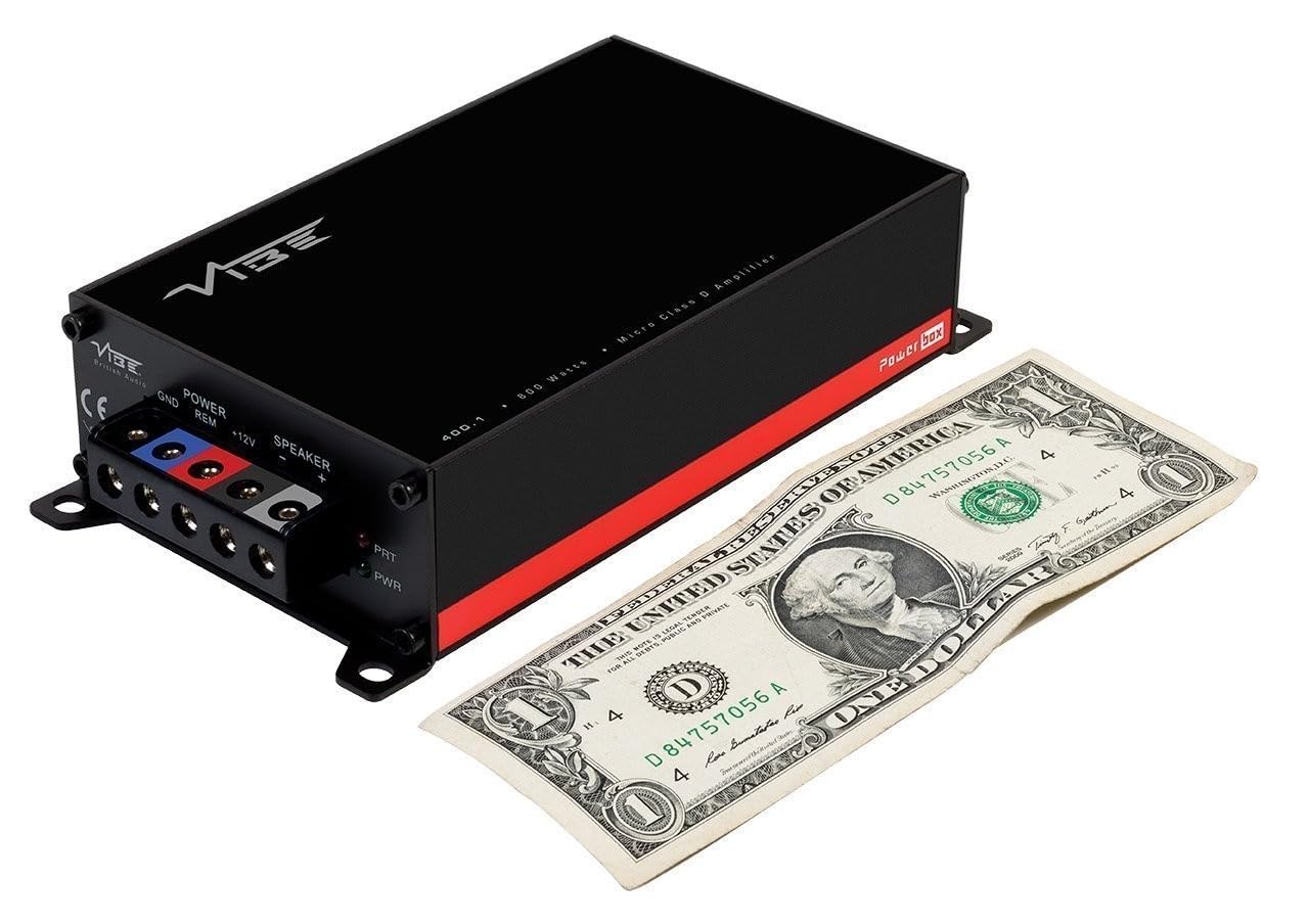
The Vibe Powerbox Micro Mono Amplifier is a compact, high-performance Class D amplifier designed for car audio systems. It delivers up to 400W RMS, making it suitable for powering subwoofers. Its small footprint allows for flexible installation options.
2. Informacje dotyczące bezpieczeństwa
- Przed rozpoczęciem jakichkolwiek prac elektrycznych należy zawsze odłączyć ujemny zacisk akumulatora pojazdu.
- Ensure all wiring is correctly routed and secured to prevent damage from moving parts or sharp edges.
- Use appropriate gauge wiring for power and speaker connections as specified in this manual to prevent overheating and potential fire hazards.
- Nie montuj ampPrzechowywać w miejscach narażonych na bezpośrednie działanie promieni słonecznych, nadmierne ciepło, wilgoć lub kurz.
- Jeśli masz jakiekolwiek wątpliwości co do któregokolwiek etapu procesu instalacji, skonsultuj się z profesjonalnym instalatorem sprzętu car audio.
- Obsługa amplifier at excessively high volumes for prolonged periods can cause hearing damage.
3. Zawartość opakowania
Przed przystąpieniem do instalacji sprawdź, czy w opakowaniu znajdują się wszystkie elementy:
- Vibe Powerbox Micro Mono Amplifier (POWERBOX400.1M-V7)
- Remote Gain Control Unit
- Kable audio RCA
- Mounting Hardware (screws, connectors)
- Instrukcja obsługi

4. Funkcje produktu
- Class D Micro Amplifier design for high efficiency and compact size.
- Ultra-compact footprint for easy and discreet installation.
- Output: 1 x 400W RMS at 1 ohm, with a maximum output of 800W.
- Dimensions: 37 x 157 x 82mm (approximately 1.46 x 6.18 x 3.23 inches).
- Compatible with Critical Link Rapid kits for simplified integration.
- Features Deltabox™ Connectivity auto turn-on.
- VIBE Sound Studio™ Active crossovers.
- 1 Ohm Stable operation.
5. Identyfikacja komponentów
5.1 Zaciski zasilania i głośnikowe

The power input section includes terminals for Ground (GND), Remote Turn-On (REM), and +12V power. The speaker output section provides terminals for connecting your subwoofer.
5.2 Input and Control Panel
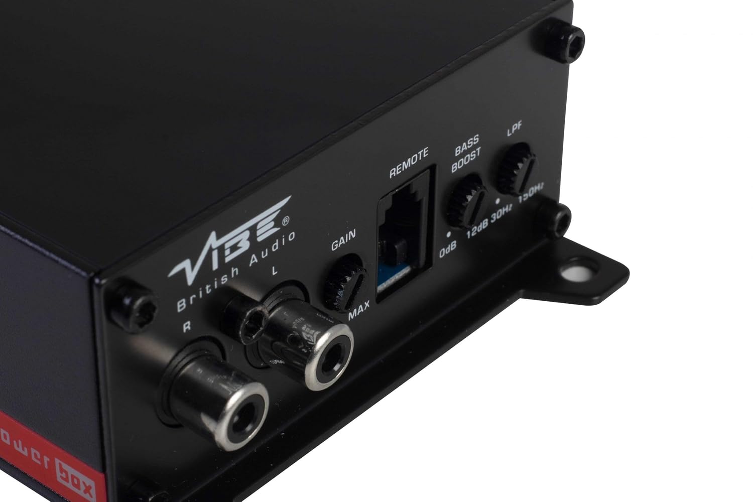
This panel features the RCA input jacks for audio signal, a Gain control knob to match the amplifier's input sensitivity to your head unit's output, a dedicated port for the remote gain control, a Bass Boost switch for enhancing low frequencies, and an LPF (Low Pass Filter) control to adjust the upper frequency limit for the subwoofer.
5.3 Remote Gain Control

The remote gain control unit connects to the amplifier via the 'REMOTE' port and allows for convenient adjustment of the subwoofer's output level from the vehicle's cabin.
6. Konfiguracja i instalacja
Proper installation is crucial for optimal performance and safety. If you are not confident in your ability to install the amplifier, seek professional assistance.
6.1 Miejsce montażu
Choose a mounting location that is dry, well-ventilated, and away from direct heat sources. The compact size of the Powerbox Micro allows for installation under seats, behind trim panels, or in other discreet locations. Ensure there is sufficient airflow around the amplifier do chłodzenia.
6.2 połączeń przewodów
Okablowanie zasilania:
- Połącz +12 V terminal to the vehicle's positive battery terminal using a suitable gauge power cable (e.g., 8 AWG or 10 AWG). Install an in-line fuse holder within 18 inches (45 cm) of the battery.
- Połącz GND terminal to a clean, unpainted metal surface on the vehicle's chassis. Ensure a good electrical connection. The ground cable should be of the same gauge as the power cable and as short as possible.
- Połącz REM (Remote Turn-On) terminal to the remote output of your head unit. This wire signals the amplifier to turn on and off with your stereo. If your head unit lacks a remote output, you can use an accessory wire that turns on with the ignition, or utilize the amplifier's auto-sense feature if applicable.
Okablowanie głośników:
- Podłącz subwoofer do Wyjście głośnika terminals (+ and -). Ensure correct polarity. This amplifier is 1 Ohm stable, allowing flexibility in subwoofer impedance configurations. Refer to your subwoofer's specifications for optimal impedance matching.
Signal Input (RCA):
- Connect the RCA output from your head unit or signal processor to the WEJŚCIE (L/P) Gniazda RCA na ampliyfikator.
Zdalna kontrola wzmocnienia:
- Plug the remote gain control unit into the dedicated ZDALNY port na amplifier. Route the cable to a convenient location for adjustment.
ISO T Harness / ISOAWK Kit:
- For simplified installation with existing stereo looms, an optional ISOAWK kit (available separately) can be used to make the amplifier compatible with an ISO T harness. This allows for plug-and-play integration for audio signal, power, and ground, potentially eliminating the need for separate battery connections.
7. Działanie
7.1 Początkowe włączenie zasilania
Po wykonaniu i sprawdzeniu wszystkich połączeń podłącz ponownie akumulator pojazdu. Włącz radioodtwarzacz. amplifier's power indicator (PWR) should illuminate green. If the protection indicator (PRT) illuminates red, refer to the troubleshooting section.
7.2 Regulacja wzmocnienia
Kontrola wzmocnienia dopasowuje się do ampczułość wejściowa przetwornika na objętość wyjściowątage jednostki głównej. Aby ustawić wzmocnienie:
- Włącz amplifier's Gain control to its minimum (MIN) setting.
- Ustaw głośność jednostki głównej na około 75–80% maksymalnej głośności.
- Zagraj dynamiczny utwór muzyczny.
- Powoli zwiększaj amplifier's Gain control until you hear distortion, then back it off slightly until the sound is clear.
The remote gain control unit allows for real-time adjustment of the subwoofer level without affecting the main system volume.
7.3 Filtr dolnoprzepustowy (LPF)
The LPF control sets the upper frequency limit for the amplifier's output. This is essential for subwoofers, ensuring they only reproduce low frequencies. Adjust the LPF knob (typically 30Hz to 150Hz) to blend the subwoofer's output seamlessly with your main speakers. A common starting point is around 80-100Hz.
7.4 Wzmocnienie basów
The Bass Boost switch provides an adjustable low-frequency enhancement. Use this feature sparingly, as excessive bass boost can lead to distortion and potential damage to your subwoofer. Adjust the boost level (0dB to 12dB) to your preference.
8. Konserwacja
- Czyszczenie: Okresowo wycieraj ampZewnętrzną powierzchnię filtra czyścić miękką, suchą ściereczką. Nie używać silnych środków chemicznych ani ściernych środków czyszczących.
- Znajomości: Regularly check all power, ground, and speaker connections to ensure they are secure and free from corrosion. Loose connections can cause performance issues or damage.
- Wentylacja: Upewnij się, że ampŻebra chłodzące urządzenia Lifier nie są zasłonięte, co pozwala na właściwe odprowadzanie ciepła.
9. Rozwiązywanie Problemów
| Problem | Możliwa przyczyna | Rozwiązanie |
|---|---|---|
| Brak zasilania (dioda LED zasilania wyłączona) | Przepalony bezpiecznik, luźne połączenie zasilania/uziemienia, brak sygnału zdalnego. | Check in-line fuse, verify +12V, GND, and REM connections. |
| Tryb ochrony (dioda PRT włączona) | Przegrzanie, zwarcie w okablowaniu głośnika, zbyt niska impedancja. | Ensure proper ventilation, check speaker wiring for shorts, verify speaker impedance. |
| Brak wyjścia dźwięku | Brak sygnału wejściowego, wzmocnienie za niskie, przewody głośnikowe odłączone. | Check RCA input connections, adjust gain, verify speaker wiring. |
| Zniekształcony dźwięk | Gain set too high, LPF incorrectly set, poor ground connection. | Reduce gain, adjust LPF, check ground connection. |
10. Specyfikacje
- Numer modelu: POWERBOX400.1M-V7
- Amplifier Typ: Klasa D Mono Ampżywsze
- Moc wyjściowa RMS: 1 x 400W RMS @ 1 Ohm
- Maksymalna moc wyjściowa: 800 W
- Wymiary produktu (dł. x szer. x wys.): Około 157 x 82 x 37 mm (6.18 x 3.23 x 1.46 cala)
- Waga: Około 1.54 funtów
- Tomtage: 12 woltów (nominalne)
- Maksymalna objętość dostawtage: 12 wolty
- Typ montażu: Montaż powierzchniowy
- Producent: Vibe Audio
- Data pierwszej dostępności: 21 lipca 2018 r.
11. Gwarancja i wsparcie
Vibe Audio products are designed and manufactured to the highest standards. For warranty information and technical support, please refer to the warranty card included with your product or visit the official Vibe Audio webZachowaj dowód zakupu na wypadek roszczeń gwarancyjnych.


