1. Wprowadzenie
This manual provides detailed instructions for the installation, setup, operation, and maintenance of your deleyCON Infrared Motion Detector, model MK3174. This device is designed to automatically switch lights or other connected loads on and off based on detected motion and ambient light conditions. It is suitable for both indoor and outdoor use.
2. Instrukcje bezpieczeństwa
- Bezpieczeństwo elektryczne: Installation and maintenance must be performed by a qualified electrician in accordance with local wiring regulations. Always disconnect power at the main circuit breaker before installation or servicing.
- Tomtage: Zapewnij objętość podażytage jest zgodne ze specyfikacją urządzenia (220-240 V AC, 50/60 Hz).
- Nośność: Nie należy przekraczać maksymalnego udźwigu określonego dla urządzenia.
- Montowanie: Urządzenie należy stabilnie zamontować na stabilnej powierzchni.
- Środowisko: Although splash-proof (IP44), avoid direct exposure to high-pressure water jets or prolonged submersion.
- Źródła ciepła: Do not install near heat sources (e.g., air conditioning vents, heating outlets) that could cause false triggers.
3. Zawartość opakowania
Sprawdź, czy w opakowaniu znajdują się wszystkie komponenty:
- 2 x deleyCON Infrared Motion Detector (MK3174)
- 1 x Instrukcja obsługi
- 4 x Screws with Dowels for mounting
4. Koniec produktuview
The deleyCON MK3174 Infrared Motion Detector features a robust design suitable for various applications. Key components include the sensor, adjustment dials, and terminal block for wiring.

Rysunek 4.1: Two deleyCON MK3174 Infrared Motion Detectors. These white, wall-mountable units are designed for both indoor and outdoor use, featuring a distinct sensor lens at the bottom.

Rysunek 4.2: Szczegółowy view of the motion detector's adjustment controls. Labelled are the sensor (1), lighting time adjustment (2, TIME), photosensitivity adjustment (3, LUX), and the protective cover (4). These controls allow users to customize the device's operation.
- Sensor (1): Detects infrared radiation (heat) from moving objects.
- TIME Adjustment (2): Controls the duration the connected light remains on after motion is detected.
- LUX Adjustment (3): Sets the ambient light level at which the sensor becomes active.
- Cover (4): Protects the wiring and mounting screws.
5. Specyfikacje
| Funkcja | Specyfikacja |
|---|---|
| Numer modelu | MK3174 |
| Kąt wykrywania | 180° |
| Zasięg wykrywania | Do 12 metrów |
| Klasa ochrony | IP44 (odporny na zachlapanie) |
| Źródło zasilania | AC 220-240V, 50/60Hz (Mains Powered) |
| Adjustable Lighting Time (TIME) | Około 10 sekund do 7 minut |
| Adjustable Photosensitivity (LUX) | Możliwość dostosowania do pracy w dzień i w nocy |
| Typ montażu | Wall Mounting, Outdoor/Indoor |
| Wymiary | Wymiary 10.4 x 7.3 x 8.25 cm |
| Waga | 220 gramów |
Note: While some product data may indicate 'Battery Powered', this device is designed for direct electrical connection to a lighting circuit (AC 220-240V) for its primary function of controlling lights.
6. Instalacja
6.1 Wybór lokalizacji
Select a suitable location for the motion detector, considering the following:
- Obszar wykrywania: Position the sensor to cover the desired area. The detector has a 180° working area and a range of up to 12 meters.
- Wysokość: Optimal mounting height is typically 1.8 to 2.5 meters for effective detection.
- Przeszkody: Avoid placing the sensor where large objects (trees, walls, vehicles) might block its field of view.
- Źródła ciepła: Do not point the sensor directly at heat sources, reflective surfaces, or areas with rapid temperature changes (e.g., exhaust vents, windows exposed to direct sunlight) to prevent false triggers.
- Ruch: For best results, position the sensor so that movement occurs across its detection zones rather than directly towards or away from it.

Rysunek 6.1: Key features and capabilities of the motion detector, including its 180° detection angle, maximum 12m range, adjustable sensor head, suitability for indoor and outdoor environments, and IP44 splash protection.

Rysunek 6.2: Example of motion detector placement within a building and its surrounding outdoor areas. Blue shaded areas indicate effective detection zones, highlighting strategic positioning for entrances, garages, and pathways.
6.2 Montaż urządzenia
- Odłącz zasilanie: Upewnij się, że główne zasilanie w miejscu instalacji jest wyłączone za pomocą wyłącznika automatycznego.
- Oddzielna baza: Carefully open the motion detector to separate the mounting base from the main unit.
- Zaznacz punkty wiercenia: Hold the mounting base against the wall at the desired installation height and mark the drilling points.
- Wiercenie otworów: Wywierć otwory w zaznaczonych punktach i włóż w nie dołączone kołki.
- Bezpieczna baza: Przymocuj podstawę montażową do ściany za pomocą dostarczonych śrub.

Rysunek 6.3: Visual guide for mounting the motion detector. This image illustrates how to detach the mounting plate, secure it to the wall with screws and dowels, and then reattach the main sensor unit.
6.3 instrukcje okablowania
OSTRZEŻENIE: All wiring must be performed by a qualified electrician. Ensure power is disconnected before proceeding.
- Blok terminala dostępowego: With the mounting base secured, access the internal terminal block.
- Podłącz przewody: Connect the electrical wires according to the diagram below.
- L (Phase/Hot): Connect the live wire (typically brown or black) to the 'L' terminal.
- N (Neutral/Ground): Connect the neutral wire (typically blue) to the 'N' terminal.
- A (Consumer/Lamp): Connect the switched live wire to the 'A' terminal. This wire goes to the light fixture or other load.
- Bezpieczne okablowanie: Sprawdź, czy wszystkie połączenia przewodów są solidne i bezpieczne.
- Ponowny montaż: Carefully reattach the main unit to the mounting base, ensuring no wires are pinched.
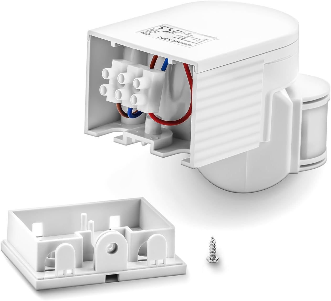
Rysunek 6.4: Internal wiring of the motion detector. This image displays the terminal block where the live (red), neutral (blue), and switched load (brown) wires are connected, ensuring proper electrical installation.
Rysunek 6.5: Detailed wiring diagram. It illustrates the connection points for the incoming power (L and N) and the outgoing connection to the lamp (A), with clear labels for Phase (hot), Zero Conductor (ground/neutral), and Consumer (lamp).
7. Konfiguracja i konfiguracja
After installation, you can adjust the sensor's settings using the 'TIME' and 'LUX' dials.
Rysunek 7.1: Adjustment dials for TIME and LUX settings. The 'TIME' dial controls the duration of illumination, while the 'LUX' dial determines the ambient light threshold for activation.
- Regulacja CZASU:
Rotate the 'TIME' dial to set how long the connected light remains on after motion is detected and stops. The range is approximately 10 seconds (minimum) to 7 minutes (maximum).
- Turn clockwise for longer duration.
- Turn counter-clockwise for shorter duration.
- Regulacja LUX:
Rotate the 'LUX' dial to set the ambient light threshold. This determines at what level of darkness the sensor will activate the light.
- Sun icon (max LUX): The sensor will activate the light both during the day and at night when motion is detected.
- Moon icon (min LUX): The sensor will only activate the light when it is dark enough (e.g., at dusk or night) and motion is detected.
Testowanie: After adjusting, restore power and test the sensor's functionality by walking through its detection area at different times of day to ensure desired operation.
8. Obsługa czujnika ruchu
Once installed and configured, the deleyCON MK3174 operates automatically:
- When motion is detected within its 180° field of view and up to 12 meters range, and the ambient light level is below the set LUX threshold, the connected light will switch on.
- The light will remain on for the duration set by the 'TIME' dial.
- If motion continues to be detected during the 'TIME' period, the timer will reset, and the light will stay on longer.
- After the set 'TIME' has elapsed and no further motion is detected, the light will automatically switch off.
Rysunek 8.1: Illustration of the motion detector's wide 180-degree detection angle and its maximum range of 12 meters, ensuring broad coverage for security and convenience.

Rysunek 8.2: Before and after comparison of an outdoor area. The left panel shows the area in darkness with the motion detector's detection field highlighted. The right panel shows the area illuminated after a person enters the detection field, demonstrating the automatic light activation.
9. Konserwacja
- Czyszczenie: Okresowo czyść soczewkę czujnika miękką,amp cloth to remove dust or dirt that may obstruct detection. Do not use abrasive cleaners or solvents.
- Kontrola: Regularly inspect the device for any signs of damage, loose wiring, or wear.
- Odłączenie zasilania: Przed przystąpieniem do czyszczenia lub kontroli należy zawsze odłączyć zasilanie.
10. Rozwiązywanie Problemów
| Problem | Możliwa przyczyna | Rozwiązanie |
|---|---|---|
| Światło nie włącza się po wykryciu ruchu. |
|
|
| Światło pozostaje włączone w sposób ciągły. |
|
|
| Światło włącza się losowo (fałszywe wyzwalacze). |
|
|
11. Gwarancja i wsparcie
deleyCON products are manufactured with quality and reliability in mind. For specific warranty information, please refer to the documentation included with your purchase or visit the official deleyCON website. If you encounter any issues that cannot be resolved using the troubleshooting guide, please contact deleyCON customer support for assistance.
Producent: deleyCON
Numer modelu: MK3174
ASIN: B077FX4XVQ
Kontakt: Refer to your purchase documentation or the deleyCON official webstrona dla danych kontaktowych.