1. Wprowadzenie
This manual provides essential information for the safe and effective installation, operation, and maintenance of the ABB B6-30-01-01 Compact 3-Pole Contactor. The B6-30-01-01 is a compact 3-pole contactor featuring one auxiliary contact and screw terminals, designed for reliable performance in applications where space is limited. It is suitable for controlling single or three-phase loads in residential, commercial, and industrial environments.
2. Informacje dotyczące bezpieczeństwa
OSTRZEŻENIE: Electrical shock hazard. Installation and maintenance should only be performed by qualified personnel. Disconnect all power before working on the contactor or connected equipment.
- Zawsze należy przestrzegać lokalnych i krajowych przepisów i regulacji dotyczących instalacji elektrycznych.
- Należy zapewnić prawidłowe uziemienie całego sprzętu.
- Sprawdź, czy objętośćtage i prąd znamionowy stycznika odpowiadają wymaganiom aplikacji.
- Do not operate the contactor if it is damaged.
3. Koniec produktuview
The ABB B6-30-01-01 mini contactor is engineered for controlling various electrical loads. Key features include:
- Kompaktowa konstrukcja: Optimized for installations with limited space.
- 3-Pole Configuration: For switching three-phase loads.
- 1 Auxiliary Contact: One normally open (NO) auxiliary contact for control circuit applications.
- Zaciski śrubowe: Secure and reliable electrical connections.
- Silent Coil: Zapewnia cichą pracę.
- Switch Position Indication: Visual indication of the contactor's state.
- Opcje montażu: Integrated possibility for DIN rail or wall mounting.
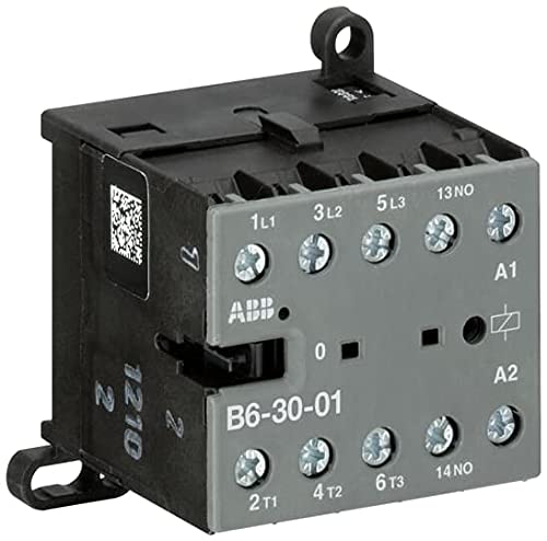
Rysunek 1: ABB B6-30-01-01 Compact Contactor. This image displays the grey and black casing of the contactor, clearly showing the screw terminals labeled 1L1, 3L2, 5L3 (inputs), 2T1, 4T2, 6T3 (outputs), A1, A2 (coil connections), and 13NO, 14NO (auxiliary contact). The ABB logo and a QR code are also visible on the unit.
4. Specyfikacje
| Numer modelu | B6-30-01-01 (Manufacturer's Part Number: GJL1211001R0011) |
| Marka | WĄTEK |
| Liczba słupów | 3 |
| Styki pomocnicze | 1 normalnie otwarty (NIE) |
| Typ terminala | Zaciski śrubowe |
| Rated Operational Power (AC-3) | Do 4 kW |
| Rated Operational Current (AC-1) | 20A / 690V |
| Wymiary (przybliżone) | 2.16 x 2.16 x 1.96 cala (54.86 x 54.86 x 49.78 mm) |
| Waga (w przybliżeniu) | 4 uncji (113 grama) |
| Montowanie | DIN Rail or Wall Mounting |
5. Instalacja
Before beginning installation, ensure all power to the circuit is disconnected. The B6-30-01-01 contactor can be mounted on a standard DIN rail or directly to a panel using screws.
5.1. Montaż
- Montaż na szynie DIN: Align the contactor's integrated clips with the DIN rail and press firmly until it clicks into place.
- Montaż na ścianie: Use appropriate screws and anchors (not supplied) to secure the contactor through the designated mounting holes on the base. Ensure the mounting surface is stable and capable of supporting the contactor's weight and any connected wiring.
5.2. Zagadnienia środowiskowe
Install the contactor in a clean, dry environment, free from excessive dust, moisture, corrosive gases, and extreme temperatures. Ensure adequate ventilation to prevent overheating.
6. Okablowanie
Refer to the wiring diagram provided with your specific application and ensure all connections are secure. Use appropriate wire gauges for the expected current load.
6.1. Power Circuit Connections
- Terminale wejściowe: Connect the incoming power lines to terminals 1L1, 3L2, I 5L3.
- Zaciski wyjściowe: Podłącz obciążenie do zacisków 2T1, 4T2, I 6T3.
6.2. Control Circuit Connections
- Zaciski cewki: Podłącz regulator voltage to terminals A1 I A2. Ensure the control voltage matches the coil voltage rating of the contactor.
- Kontakt pomocniczy: The normally open (NO) auxiliary contact is connected to terminals 13NIE I 14NIE. This contact closes when the main coil is energized.
Tighten all screw terminals to the manufacturer's specified torque to ensure reliable electrical contact and prevent loose connections.
7. Działanie
The ABB B6-30-01-01 contactor operates by energizing its coil. When the appropriate control voltage is applied to terminals A1 and A2, the coil creates a magnetic field, pulling the main contacts closed and connecting the power circuit from 1L1/3L2/5L3 to 2T1/4T2/6T3. Simultaneously, the auxiliary contact (13NO-14NO) will close.
- Energizowanie cewki: Applying the rated control voltage to A1 and A2 will close the main and auxiliary contacts.
- Odłączanie cewki od napięcia: Usuwanie głośności kontrolnejtage from A1 and A2 will cause the coil to de-energize, opening the main and auxiliary contacts.
- Switch Position Indication: A visual indicator on the contactor provides feedback on the current state of the main contacts (e.g., '0' for open, 'I' for closed, or a similar marking).
8. Konserwacja
Regular maintenance helps ensure the longevity and reliable operation of the contactor. Always disconnect power before performing any maintenance.
- Kontrola wizualna: Periodically inspect the contactor for any signs of damage, discoloration, loose connections, or excessive dust accumulation.
- Czyszczenie: Use a dry, soft cloth or compressed air to remove dust and debris from the contactor's exterior. Do not use solvents or abrasive cleaners.
- Szczelność zacisku: Check and re-tighten all screw terminals as necessary to prevent overheating due to loose connections.
- Noszenie kontaktowe: While internal contacts are generally not user-serviceable, excessive arcing or contact welding may indicate a need for replacement.
9. Rozwiązywanie Problemów
Jeśli stycznik nie działa zgodnie z oczekiwaniami, należy wziąć pod uwagę następujące typowe problemy:
- Stycznik nie jest zasilany:
- Sprawdź, czy głośność sterowaniatage is present at terminals A1 and A2.
- Sprawdź objętość sterowaniatage matches the coil's rated voltage.
- Inspect control circuit wiring for loose connections or breaks.
- Contactor Energizes But Load Does Not Receive Power:
- Ensure main power is supplied to 1L1, 3L2, 5L3.
- Check connections to the load at 2T1, 4T2, 6T3.
- Verify the contactor's switch position indicator shows 'closed'.
- Przegrzanie:
- Sprawdź, czy nie ma poluzowanych połączeń zacisków.
- Ensure the load current does not exceed the contactor's ratings.
- Verify adequate ventilation around the contactor.
If issues persist after troubleshooting, contact qualified electrical personnel or ABB technical support.
10. Informacje o gwarancji
Specific warranty terms and conditions for the ABB B6-30-01-01 contactor are provided by ABB at the time of purchase. Please refer to the documentation included with your product or visit the official ABB webSzczegółowe informacje o gwarancji znajdziesz na stronie. Zachowaj dowód zakupu na wypadek roszczeń gwarancyjnych.
11. Wsparcie techniczne
For technical assistance, product inquiries, or service, please contact ABB customer support. Contact information can typically be found on the official ABB website or through your local ABB distributor.
Oficjalny przedstawiciel ABB Webstrona: www.abb.com


