1. Wprowadzenie
This manual provides detailed instructions for the installation, operation, and maintenance of the Cotek SP-1000-224 Pure Sine Wave Inverter. This inverter is designed to convert 24VDC power to 230VAC, providing a stable and reliable power source for various applications.
Główne cechy:
- Czysta fala sinusoidalna dla wrażliwej elektroniki.
- Power ON / OFF remote control capability (Green Terminal).
- Input & output fully isolated for enhanced safety.
- Temperature & load controlled cooling fan for optimal performance.
- Przyjazny dla użytkownika interfejs.
- Częstotliwość wyjściowa (50/60 Hz) wybierana za pomocą przełącznika DIP.
- Objętość wyjściowatagMożna je wybierać za pomocą przełącznika DIP.
- Power saving mode adjustable via variable resistor.
- 3-color LED status indicators for easy monitoring.
- Kompleksowa ochrona wejściowa: odwrotna polaryzacja (bezpiecznik), zbyt niska głośnośćtage, ponad tomtage.
- Solidna ochrona wyjściowa: zwarcie, przeciążenie, przegrzanie.
- Obudowa aluminiowa do zastosowań wewnętrznych typu 1.
- Zatwierdzone przez E13 / UL / CE / FCC.
2. Informacje dotyczące bezpieczeństwa
WARNING: Please read and understand all safety instructions before installing or operating this inverter. Failure to follow these instructions may result in electric shock, fire, serious injury, or death.
- Zagrożenie elektryczne: This unit produces high voltage. Nie otwierać falownika casing. Wszelkie prace serwisowe powierzaj wykwalifikowanemu personelowi.
- Bezpieczeństwo baterii: Work in a well-ventilated area. Batteries can produce explosive gases. Do not smoke or allow sparks or flames near the battery.
- Prawidłowa wentylacja: Ensure adequate airflow around the inverter. Do not block ventilation openings.
- Warunki środowiskowe: Do not expose the inverter to rain, moisture, or excessive dust. Operate in a dry, cool environment.
- Grunt: The inverter must be properly grounded. Follow all local and national electrical codes.
- Nośność: Do not exceed the inverter's rated power output. Overloading can cause damage to the inverter and connected devices.
- Ostrzeżenie dotyczące kalifornijskiej propozycji 65: Produkt ten może zawierać substancje objęte ostrzeżeniem zawartym w kalifornijskiej Propozycji 65.
3. Koniec produktuview i komponenty
Familiarize yourself with the various parts of your Cotek SP-1000-224 Pure Sine Wave Inverter.

Rysunek 3.1: Kątowy view of the Cotek SP-1000-224 Pure Sine Wave Inverter, showing its blue aluminum casing and grey end caps with ventilation and connection ports.

Rysunek 3.2: Front panel of the inverter, featuring the AC output socket (Schuko type), a power switch, LED indicators, and DIP switches for configuration.

Rysunek 3.3: Rear panel of the inverter, showing the DC input terminals for battery connection, a remote control port (RJ45), and a green terminal block for remote ON/OFF control.

Rysunek 3.4: Strona view of the inverter, highlighting its robust blue aluminum heat sink casing designed for efficient heat dissipation.
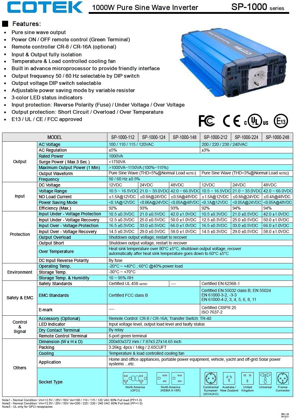
Rysunek 3.5: A detailed table outlining the features and technical specifications of the Cotek SP-1000 series inverters, including input/output parameters, protections, and certifications.

Rysunek 3.6: Mechanical drawings providing dimensions of the inverter, along with power voltage and power temperature curves illustrating performance characteristics.
4. Konfiguracja i instalacja
4.1 Wybór lokalizacji:
- Install the inverter in a dry, cool, and well-ventilated area.
- Unikaj bezpośredniego światła słonecznego, źródeł ciepła i wilgoci.
- Ensure sufficient clearance around the inverter for proper airflow, especially around the cooling fan and ventilation openings.
- Mount the inverter securely on a stable, non-combustible surface.
4.2 DC Input Connection:
- Upewnij się, że wyłącznik zasilania falownika jest w pozycji WYŁĄCZONY.
- Connect the positive (+) terminal of the 24VDC battery bank to the positive (+) DC input terminal on the inverter.
- Connect the negative (-) terminal of the 24VDC battery bank to the negative (-) DC input terminal on the inverter.
- Aby zminimalizować głośność, należy używać kabli o odpowiednim rozmiarze.tage drop and ensure safe operation. Refer to electrical standards for cable sizing.
- Sprawdź, czy wszystkie połączenia są dobrze dokręcone i bezpieczne.
4.3 AC Output Connection:
- Plug your AC appliances directly into the AC output socket on the inverter.
- Ensure the total power consumption of all connected appliances does not exceed the inverter's 1000W continuous output rating.
4.4 Uziemienie:
Proper grounding is essential for safety. Connect the inverter's chassis ground terminal to a reliable earth ground using a suitable grounding wire. Consult local electrical codes for specific grounding requirements.
4.5 Remote Control (Optional):
The inverter supports remote ON/OFF control via the green terminal block or an optional RJ45 remote control unit. Refer to the accessory manual for detailed instructions on connecting and using the remote control.
4.6 DIP Switch Configuration:
The inverter features DIP switches on the front panel to select output frequency (50/60 Hz) and output voltage. Refer to the table below for common settings. Ensure the inverter is OFF before changing DIP switch settings.
| Ustawienie | Pozycja przełącznika DIP |
|---|---|
| Częstotliwość wyjściowa 50Hz | Switch 1: OFF, Switch 2: OFF (Example, refer to actual product manual/Figure 3.5) |
| Częstotliwość wyjściowa 60Hz | Switch 1: ON, Switch 2: OFF (Example, refer to actual product manual/Figure 3.5) |
| Objętość wyjściatage 230 V AC | Switch 3: ON, Switch 4: OFF (Example, refer to actual product manual/Figure 3.5) |
Note: The exact DIP switch configurations for specific voltage and frequency settings are detailed in the product's full technical specifications (refer to Figure 3.5). Always verify settings before operation.
5. Działanie
5.1 Powering On the Inverter:
- Ensure all DC and AC connections are secure and correct.
- If using the remote control, ensure it is connected and in the ON position.
- Flip the main power switch on the inverter's front panel to the "ON" position.
- Observe the 3-color LED status indicators. A green light indicates normal operation.
5.2 LED Status Indicators:
- Zielony: Normalna praca.
- Żółty/bursztynowy: Warning (e.g., input voltage slightly low/high, minor overload). The inverter may continue to operate but requires attention.
- Czerwony: Fault condition (e.g., severe overload, short circuit, over-temperature, critical input voltage). The inverter will shut down to protect itself and connected devices.
5.3 Power Saving Mode:
The inverter features a power saving mode, adjustable via a variable resistor. This mode reduces power consumption when no load or a very light load is detected. Adjust the resistor to set the sensitivity for entering/exiting power saving mode.
5.4 Powering Off the Inverter:
- Turn off all connected AC appliances.
- Flip the main power switch on the inverter's front panel to the "OFF" position.
- If using a remote control, turn it off as well.
6. Konserwacja
Regularna konserwacja zapewnia długowieczność i niezawodną pracę falownika.
- Czyszczenie: Okresowo czyść zewnętrzną część falownika suchą, miękką ściereczką. Nie używaj płynnych środków czyszczących ani rozpuszczalników. Upewnij się, że otwory wentylacyjne są wolne od kurzu i zanieczyszczeń.
- Znajomości: Periodically check all DC and AC connections to ensure they are tight and free from corrosion. Loose connections can cause overheating and poor performance.
- Wentylacja: Ensure the cooling fan and ventilation grilles are not obstructed. The fan operates based on temperature and load, so ensure it can draw and expel air freely.
- Stan baterii: Monitoruj stan swojego akumulatora. Słaby lub uszkodzony akumulator może negatywnie wpłynąć na wydajność i żywotność falownika.
WARNING: Do not attempt to service the inverter yourself. There are no user-serviceable parts inside. Refer all servicing to qualified personnel.
7. Rozwiązywanie Problemów
This section provides solutions to common issues you might encounter with your inverter. If the problem persists after following these steps, contact customer support.
| Problem | Możliwa przyczyna | Rozwiązanie |
|---|---|---|
| Inverter does not turn on (No LED indication) |
|
|
| Red LED is on, inverter shuts down |
|
|
| Yellow/Amber LED is on |
|
|
| Brak wyjścia AC |
|
|
8. Specyfikacje techniczne
The following table provides detailed technical specifications for the Cotek SP-1000-224 Pure Sine Wave Inverter. For a comprehensive overview, refer to Figure 3.5.
| Parametr | Value (SP-1000-224) |
|---|---|
| Model | SP-1000-224 |
| Objętość wyjścia ACtage | 230VAC (selectable) |
| Objętość wejścia DCtage | 24 V prądu stałego |
| Ciągła moc | 1000 W |
| Surge Power (3 sec) | 1750VA |
| Przebieg wyjściowy | Czysta fala sinusoidalna (THD < 3%) |
| Częstotliwość wyjściowa | 50/60 Hz (do wyboru) |
| Wydajność (maks.) | 92% |
| Wejście pod objtage Ochrona | 21.0 ± 0.5 V DC |
| Wejście przez Voltage Ochrona | 33.0 ± 0.5 V DC |
| Temperatura pracy | -20°C ~ +40°C (60% power load) |
| Wymiary (dł. x szer. x wys.) | 17 x 10 x 6 cala (w przybliżeniu) |
| Waga | 8.94 funta |
| Certyfikaty | Certyfikat E13 / UL / CE / FCC |
Note: Specifications are subject to change without notice. Always refer to the product label or manufacturer's official documentation for the most accurate and up-to-date information.
9. Informacje o gwarancji
COTEK products are manufactured to high quality standards. For specific warranty terms and conditions, including duration and coverage, please refer to the warranty card included with your product or visit the official COTEK webZachowaj dowód zakupu na wypadek roszczeń gwarancyjnych.
Typical warranties cover defects in materials and workmanship under normal use. Damage caused by improper installation, misuse, abuse, or unauthorized modifications is generally not covered.
10. Obsługa klienta
If you have any questions, require technical assistance, or need to report an issue with your Cotek SP-1000-224 Pure Sine Wave Inverter, please contact COTEK customer support or your authorized dealer.
Kontaktując się z pomocą techniczną, przygotuj następujące informacje:
- Product Model: SP-1000-224
- Serial Number (if applicable, usually found on the product label)
- Data zakupu
- A detailed description of the issue you are experiencing.
For the most up-to-date contact information, please visit the official COTEK webstrona: www.cotek.com.tw (To jest symbol zastępczy URL, proszę sprawdzić faktycznego producenta webStrona).


