1. Wprowadzenie
This manual provides comprehensive instructions for the installation, operation, and maintenance of the Supermicro X10SLM+-LN4F motherboard. Designed for server applications, this motherboard features an LGA1150 socket, Intel C224 PCH, DDR3 memory support, and multiple Gigabit Ethernet ports. Please read this manual thoroughly before proceeding with installation to ensure proper setup and optimal performance.
2. Koniec produktuview
The Supermicro X10SLM+-LN4F is a microATX server motherboard built for reliability and performance. Key features include:
- LGA1150 Socket for Intel Xeon E3-1200 v3/v4 and 4th Gen Core i3 processors.
- Intel C224 PCH chipset.
- Four DDR3 DIMM slots supporting up to 64GB ECC/non-ECC UDIMM.
- Multiple SATA3 (6Gbps) ports.
- Integrated quad Gigabit Ethernet ports.
- USB 3.0 and USB 2.0 support.
- VGA output for integrated graphics.
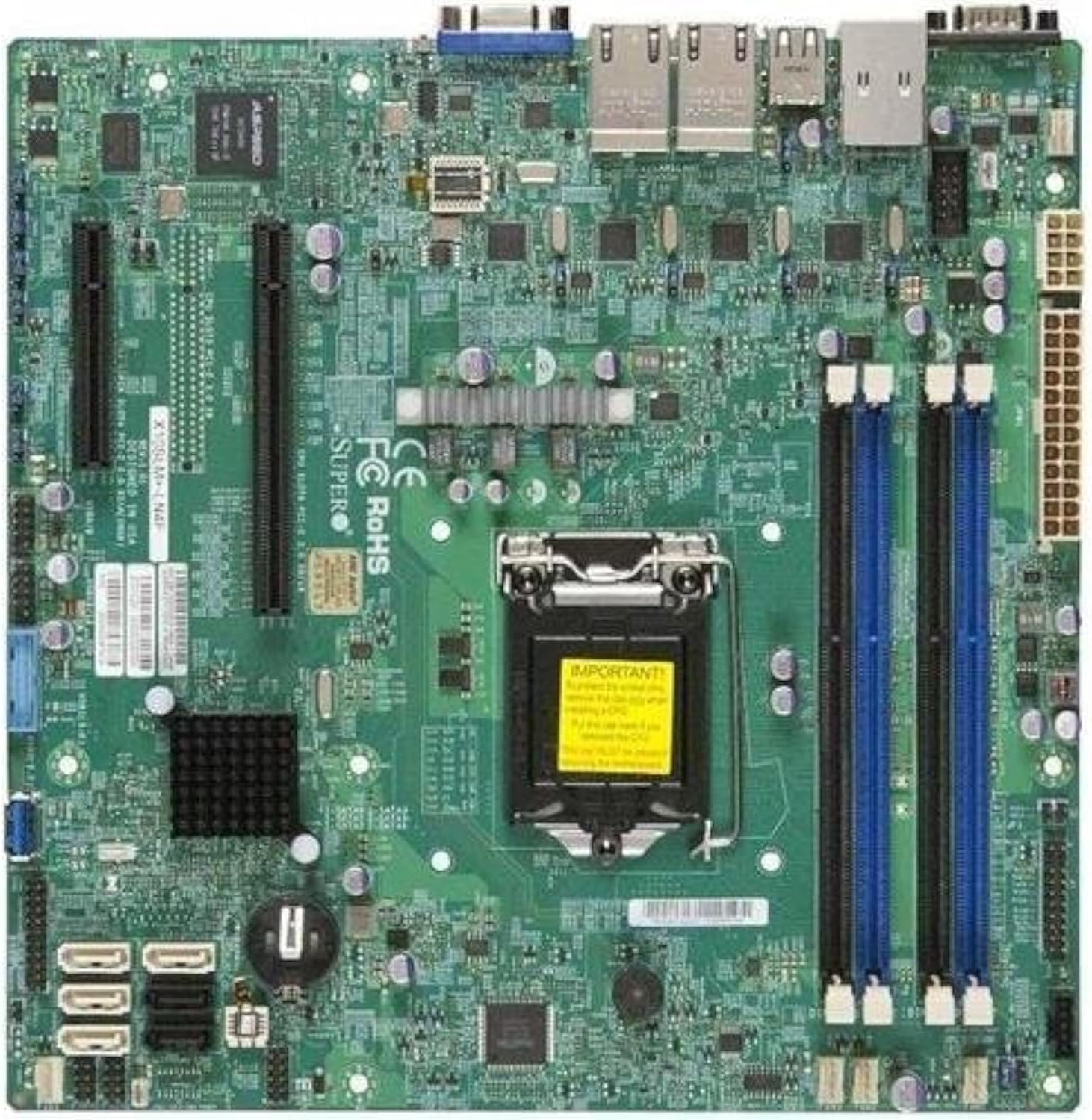
Rysunek 2.1: Z góry na dół view of the Supermicro X10SLM+-LN4F motherboard, showing the CPU socket, DIMM slots, PCIe slots, and various connectors.

Rysunek 2.2: Kątowy view of the motherboard, highlighting the layout of components and expansion slots.
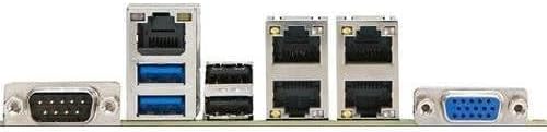
Rysunek 2.3: Rear I/O panel of the Supermicro X10SLM+-LN4F motherboard, featuring multiple LAN ports, USB ports, and serial ports.
3. Konfiguracja i instalacja
Before beginning installation, ensure your system is powered off and disconnected from the power source. Wear an anti-static wrist strap to prevent electrostatic discharge (ESD) damage to components.
3.1. Instalacja procesora
- Znajdź gniazdo procesora LGA1150 na płycie głównej.
- Delikatnie naciśnij dźwignię obciążenia i pociągnij ją na bok, aby otworzyć ramkę mocującą gniazdo procesora.
- Dokładnie dopasuj trójkątny znak na procesorze do odpowiadającego mu znaku na gnieździe.
- Place the CPU into the socket without forcing it.
- Zamknij ramę mocującą i zabezpiecz ją dźwignią ładunkową.
- Nałóż cienką, równomierną warstwę pasty termoprzewodzącej na zintegrowany radiator procesora (IHS).
- Zainstaluj chłodzenie procesora zgodnie z instrukcją producenta.
3.2. Instalacja pamięci (RAM)
- Locate the four DDR3 DIMM slots. For optimal performance, refer to the motherboard's specific memory population guidelines, typically starting with slots closest to the CPU or specific colored slots for dual-channel configurations.
- Otwórz zatrzaski mocujące na obu końcach gniazda DIMM.
- Dopasuj wycięcie na module pamięci DDR3 do wypustki w gnieździe DIMM.
- Wsuń moduł pamięci mocno do gniazda, aż zatrzaski mocujące zatrzasną się na swoim miejscu.
- Sprawdź, czy oba klipsy są całkowicie zamknięte i moduł jest prawidłowo osadzony.
3.3. Instalacja urządzenia pamięci masowej
Connect SATA storage devices (HDDs/SSDs) to the SATA ports on the motherboard using SATA data cables. Connect the power cables from your power supply unit (PSU) to the storage devices.
3.4. Instalacja karty rozszerzeń
This motherboard features PCI Express (PCIe) slots. To install an expansion card:
- Remove the corresponding slot cover from your chassis.
- Wyrównaj kartę rozszerzeń z gniazdem PCIe.
- Dociśnij mocno, aż karta zostanie całkowicie osadzona w gnieździe.
- Przymocuj kartę do obudowy za pomocą śrubki lub klipsa mocującego.
3.5. Połączenia zasilania
- Złącze zasilania ATX 24-pinowe: Connect the main 24-pin power cable from your PSU to the ATX power connector on the motherboard.
- 8-pin EPS/CPU Power Connector: Connect the 8-pin (or 4+4 pin) CPU power cable from your PSU to the EPS connector near the CPU socket.
3.6. Połączenia panelu przedniego i tylnego wejścia/wyjścia
- Złącza na panelu przednim: Connect the power switch, reset switch, power LED, and HDD activity LED cables from your chassis to the corresponding pins on the motherboard's front panel header. Refer to the motherboard's silkscreen labels for correct orientation.
- Nagłówki USB: Connect front panel USB ports to the onboard USB headers.
- Nagłówki audio: Connect front panel audio jacks to the onboard audio header.
- Tylny panel I/O: Connect peripherals such as keyboard, mouse, monitor (via VGA), and network cables (to the Gigabit Ethernet ports) to the rear I/O panel.
4. Instrukcja obsługi
4.1. Pierwsze włączenie zasilania i konfiguracja BIOS/UEFI
- After all components are installed and connected, connect the power cord to the PSU and turn on the power switch on the PSU.
- Press the power button on your chassis.
- Podczas testu POST (Power-On Self-Test) naciskaj wielokrotnie przycisk USUNĄĆ or F2 key (or as indicated on screen) to enter the BIOS/UEFI setup utility.
- In the BIOS/UEFI, configure essential settings such as date and time, boot order, and enable/disable specific features as required for your operating system and hardware.
- Zapisz zmiany i wyjdź z BIOS-u/UEFI. System uruchomi się ponownie.
4.2. Instalacja systemu operacyjnego
To install an operating system (e.g., Windows, Linux, VMware ESXi):
- Insert the operating system installation media (USB drive or DVD) into the system.
- Boot from the installation media (you may need to adjust the boot order in BIOS/UEFI).
- Follow the on-screen prompts to install the operating system on your chosen storage device.
- After installation, install all necessary drivers for the motherboard components (chipset, LAN, VGA, etc.) from the Supermicro webwitrynę lub dostarczoną płytę ze sterownikami.
5. Konserwacja
Regularna konserwacja pomaga zapewnić długowieczność i stabilną pracę płyty głównej i systemu.
5.1. Czyszczenie
- Periodically clean dust from the motherboard and system components using compressed air. Ensure the system is powered off and unplugged before cleaning.
- Unikaj stosowania płynnych środków czyszczących bezpośrednio na podzespołach.
- Ensure proper airflow within the chassis by keeping fan vents clear.
5.2. Firmware and Driver Updates
- Sprawdź Supermikro website periodically for updated BIOS/UEFI firmware and drivers for your motherboard model.
- Follow the provided instructions carefully when updating firmware to avoid system instability.
5.3. Zagadnienia środowiskowe
- Operate the motherboard within recommended temperature and humidity ranges to prevent damage.
- Ensure adequate ventilation in the server chassis.
6. Rozwiązywanie Problemów
W tej sekcji znajdziesz rozwiązania typowych problemów, na jakie możesz natrafić.
6.1. Brak zasilania / Brak testu POST (autotest po włączeniu zasilania)
- Verify that the power supply unit (PSU) is connected correctly to the motherboard (24-pin ATX and 8-pin EPS connectors).
- Ensure the PSU is switched on and receiving power from the wall outlet.
- Sprawdź, czy kabel przełącznika zasilania na panelu przednim jest prawidłowo podłączony do złącza płyty głównej.
- Ponownie zamontuj procesor, moduły pamięci RAM i wszelkie karty rozszerzeń.
- Aby zidentyfikować problem, spróbuj uruchomić komputer, używając tylko niezbędnych podzespołów (procesora, jednej kości pamięci RAM, chłodzenia procesora).
- Listen for beep codes from the system speaker, which can indicate specific hardware failures. Refer to the Supermicro website for beep code interpretations.
6.2. Problemy z wyświetlaniem
- Ensure the monitor is properly connected to the motherboard's VGA port.
- Sprawdź, czy monitor jest włączony i ustawiony na prawidłowe źródło sygnału wejściowego.
- If using a discrete graphics card, ensure it is properly seated and connected to power (if required).
6.3. System operacyjny nie uruchamia się
- Check the boot order in the BIOS/UEFI to ensure the correct storage device is prioritized.
- Verify that the operating system is installed correctly on the storage device.
- Ensure SATA data and power cables are securely connected to the storage device and motherboard.
7. Specyfikacje
Below are the technical specifications for the Supermicro X10SLM+-LN4F motherboard:
| Funkcja | Szczegół |
|---|---|
| Marka | Supermikro |
| Nazwa modelu | X10SLM+-LN4F-B |
| Gniazdo procesora | LGA1150 |
| Typ chipsetu | Intel® C224 |
| Technologia pamięci RAM | Pamięć DDR3 SDRAM |
| Prędkość pamięci | 1600MHz |
| Pojemność pamięci masowej | Do 64 GB |
| Liczba portów USB 2.0 | 2 (wejście/wyjście tylne) |
| Interfejs karty graficznej | Integrated, PCI |
| Kompatybilne urządzenia | Serwer |
| Platforma | Windows 10 |
| Waga przedmiotu | 5.8 funta |
| Wymiary produktu (dł. x szer. x wys.) | 10 x 10 x 2 cala |
| Data pierwszej dostępności | 4 czerwca 2013 r. |
Note: Specifications are subject to change without notice. For the most current information, please refer to the official Supermicro product page.
8. Gwarancja i wsparcie
For detailed warranty information, please refer to the warranty card included with your product or visit the official Supermicro website. Technical support is available through Supermicro's customer service channels, including their support portal, email, and phone. Please have your product model number (X10SLM+-LN4F) and serial number ready when contacting support.
For the latest drivers, BIOS updates, and additional documentation, please visit: www.supermicro.com


