1. Wprowadzenie
The Velleman DVM810 is a compact and economical 3 1/2 digit digital multimeter designed for measuring DC and AC voltages, DC currents, resistance, and for performing diode and transistor (hFE) tests. It features overload protection and automatic polarity indication, making it suitable for hobbyists, field use, and workshops. This manual provides essential information for the safe and effective operation of your DVM810 multimeter.
2. Funkcje produktu
- Automatic polarity indication
- Tomtage measurements: AC 500V and DC 500V maximum
- Current measurements: DC 10A maximum (0.2A fused, 10A unfused)
- Resistance measurements: Up to 2MΩ
- Diode and transistor (hFE) test functions
- Zabezpieczenie przed przeciążeniem
- Compact design with 3 1/2 digit LCD display
3. Zawartość opakowania
Sprawdź zawartość paczki, aby upewnić się, że znajdują się w niej wszystkie elementy:
- Multimetr cyfrowy Velleman DVM810
- Przewody pomiarowe (jeden czerwony, jeden czarny)
- Instrukcja obsługi
4. Ważne informacje dotyczące bezpieczeństwa
Read all safety warnings and instructions carefully before using this product. Failure to follow these instructions may result in electric shock, fire, or serious injury.
- Przed dokonaniem jakichkolwiek pomiarów należy zawsze upewnić się, że multimetr jest ustawiony na właściwą funkcję i zakres.
- Never exceed the maximum input limits for any range. The maximum voltage for AC/DC is 500V.
- Do not attempt to measure current on circuits with voltages przekraczające 250V.
- Przed każdym użyciem sprawdź przewody pomiarowe pod kątem uszkodzonej izolacji lub odsłoniętego metalu. Uszkodzone przewody należy natychmiast wymienić.
- Nie używaj multimetru, jeśli wygląda na uszkodzony lub jego obudowa jest otwarta.
- Exercise extreme caution when working with live circuits. Use appropriate personal protective equipment.
- Zawsze odłączaj zasilanie obwodu i rozładuj ładunki o wysokim napięciutage capacitors before measuring resistance or performing diode/transistor tests.
- Replace the battery when the low battery indicator appears on the display to ensure accurate readings.
5. Koniec produktuview
Familiarize yourself with the components of your Velleman DVM810 multimeter:
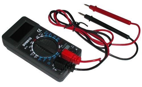
Figure 1: Velleman DVM810 Digital Multimeter. This image displays the front view of the compact multimeter, highlighting its liquid crystal display (LCD), the central rotary function switch, and the input jacks for test leads at the bottom.
- Wyświetlacz LCD: Shows measurement readings, units, and polarity.
- Przełącznik obrotowy: Służy do wyboru żądanej funkcji pomiarowej i zakresu.
- Gniazda wejściowe:
- Gniazdo COM: Common (negative) input for all measurements. Connect the black test lead here.
- Gniazdo VΩmA: Pozytywny wkład dla wolumenutage, resistance, and current measurements up to 200mA. Connect the red test lead here.
- Gniazdo 10A: Positive input for high current measurements (up to 10A). Connect the red test lead here for 10A measurements.
- Przewody testowe: Red and black leads used to connect the multimeter to the circuit under test.
6. Konfiguracja
6.1 Instalacja baterii
The DVM810 multimeter requires a 9V battery (not always included). To install or replace the battery:
- Ensure the multimeter is turned OFF (rotary switch set to OFF).
- Znajdź pokrywę komory baterii z tyłu urządzenia.
- Remove the screw(s) securing the cover and carefully lift it off.
- Podłącz nową baterię 9 V do zacisku baterii, zwracając uwagę na prawidłową biegunowość.
- Umieść baterię w komorze i załóż pokrywę, zabezpieczając ją śrubą(-ami).
6.2 Podłączanie przewodów pomiarowych
Aby zapewnić dokładność i bezpieczeństwo pomiarów, zawsze podłączaj przewody pomiarowe prawidłowo:
- Włóż czarny przewód pomiarowy do KOM (zwykły) walec.
- Dla większości pomiarów (objętośćtage, resistance, diode, hFE, and current up to 200mA), insert the red test lead into the VΩmA podnośnik.
- W przypadku pomiarów dużego prądu (do 10A) włóż czerwony przewód pomiarowy do 10A podnośnik.
7. Instrukcja obsługi
Before making any measurement, ensure the test leads are correctly connected and the rotary switch is set to the appropriate function and range.
7.1 Pomiar objętości prądu stałegotage (V=)
- Włóż czerwony przewód do VΩmA jack and the black lead into the KOM podnośnik.
- Ustaw przełącznik obrotowy na żądaną wartość DC Vol.tage (V=) range. Start with the highest range if the voltage jest nieznany.
- Connect the test leads across the component or circuit to be measured (in parallel).
- Przeczytaj tomtage value on the LCD display. The display will show the correct polarity.
7.2 Pomiar objętości prądu przemiennegotagmi (V~)
- Włóż czerwony przewód do VΩmA jack and the black lead into the KOM podnośnik.
- Ustaw przełącznik obrotowy na żądaną głośność prądu zmiennego.tage (V~) range. Start with the highest range if the voltage jest nieznany.
- Connect the test leads across the component or circuit to be measured (in parallel).
- Przeczytaj tomtage wartość na wyświetlaczu LCD.
7.3 Pomiar prądu stałego (A=)
Uwaga: Nigdy nie podłączaj multimetru równolegle do miernika objętości.tagPodczas pomiaru prądu należy unikać źródła prądu, gdyż może to spowodować przepalenie bezpiecznika lub uszkodzenie miernika.
- Determine the expected current. For currents up to 200mA, insert the red lead into the VΩmA jack. For currents up to 10A, insert the red lead into the 10A jack. Always insert the black lead into the KOM podnośnik.
- Set the rotary switch to the appropriate DC Current (A=) range. Start with the highest range if the current is unknown.
- Turn off power to the circuit. Open the circuit where the current is to be measured.
- Podłącz multimetr szeregowo do obwodu.
- Restore power to the circuit and read the current value on the LCD display.
7.4 Pomiar rezystancji (Ω)
Caution: Ensure the circuit is completely de-energized and all capacitors are discharged before measuring resistance.
- Włóż czerwony przewód do VΩmA jack and the black lead into the KOM podnośnik.
- Set the rotary switch to the desired Resistance (Ω) range. Start with a higher range if the resistance is unknown.
- Podłącz przewody pomiarowe do mierzonego elementu.
- Odczytaj wartość rezystancji na wyświetlaczu LCD.
7.5 Test diody
Caution: Ensure the diode is disconnected from the circuit or the circuit is de-energized before testing.
- Włóż czerwony przewód do VΩmA jack and the black lead into the KOM podnośnik.
- Set the rotary switch to the Diode symbol (→|).
- Podłącz czerwony przewód do anody, a czarny przewód do katody diody. Na wyświetlaczu pojawi się napięcie przewodzenia.tagspadek napięcia (zwykle 0.5 V do 0.8 V dla diod krzemowych).
- Reverse the leads. The display should show 'OL' (Overload) for a good diode. If it shows a reading in both directions or 'OL' in both directions, the diode may be faulty.
7.6 Test tranzystora (hFE)
Caution: Ensure the transistor is disconnected from the circuit before testing.
- Włóż czerwony przewód do VΩmA jack and the black lead into the KOM podnośnik.
- Ustaw przełącznik obrotowy w pozycji hFE.
- Identify if the transistor is NPN or PNP. Insert the transistor's emitter, base, and collector leads into the corresponding holes in the hFE socket on the multimeter.
- Odczytaj wartość hFE (wzmocnienia prądu stałego) na wyświetlaczu LCD.
8. Specyfikacje
| Parametr | Wartość |
|---|---|
| Marka | Velleman |
| Numer modelu | DVM810 |
| Typ pomiaru | Multimetr |
| Objętość DCtage Zakres | Do 500V |
| AC Objętośćtage Zakres | Do 500V |
| Zakres prądu stałego | Up to 10A (0.2A fused, 10A unfused) |
| Zakres oporu | Do 2MΩ |
| Test Diody | Tak |
| Test tranzystora (hFE) | Tak |
| Wyświetlacz | 3 1/2-cyfrowy wyświetlacz LCD |
| Źródło zasilania | Bateria 9V (brak w zestawie) |
| Wymiary | Około 3.70" x 1.81" x 1.03" |
| Waga przedmiotu | Około 3.2 uncji (0.2 funta) |
| UPC | 836479002272 |
9. Konserwacja
9.1 Wymiana baterii
When the low battery indicator appears on the LCD, replace the 9V battery as described in Section 6.1. A weak battery can lead to inaccurate readings.
9.2 Czyszczenie
Aby wyczyścić multimetr, przetrzyj obudowę miękką szmatką.amp cloth and a mild detergent. Do not use abrasives or solvents. Ensure the unit is completely dry before use.
9.3 Kontrola przewodów pomiarowych
Regularly inspect the test leads for any signs of damage, such as cracked insulation, exposed wires, or loose connections. Replace damaged leads immediately to prevent electric shock hazards.
10. Rozwiązywanie Problemów
- Brak obrazu lub słaby obraz: Sprawdź baterię. W razie potrzeby wymień.
- Nieprawidłowe odczyty:
- Upewnij się, że przełącznik obrotowy jest ustawiony na właściwą funkcję i zakres.
- Sprawdź pojemność akumulatoratage; wymień jeśli jest niski.
- Sprawdź, czy przewody pomiarowe są prawidłowo podłączone i nie są uszkodzone.
- Podczas pomiaru rezystancji należy upewnić się, że obwód jest odłączony od napięcia.
- Wyświetlono komunikat „OL” (Przeciążenie): Zmierzona wartość przekracza wybrany zakres. Wybierz wyższy zakres lub upewnij się, że obwód mieści się w zakresie możliwości miernika.
- Fuse blown (during current measurement): If the meter stops measuring current, the internal fuse may have blown. Refer to a qualified technician for fuse replacement.
11. Gwarancja i wsparcie
Warranty information for the Velleman DVM810 Digital Multimeter is typically provided with your purchase documentation or can be found on the official Velleman website. For technical support, service, or further inquiries, please refer to the contact information provided by your retailer or the manufacturer's official support channels.


