1. Wprowadzenie
This manual provides instructions for the safe and effective use of the Sealey MM19 Digital Multimeter. The MM19 is a general-purpose multimeter designed for measuring various electrical parameters, including AC and DC voltage, DC current, resistance, audible continuity, and diode/transistor verification. Please read this manual thoroughly before operation and retain it for future reference.
2. Informacje dotyczące bezpieczeństwa
Always observe basic safety precautions when using electrical test equipment to reduce the risk of fire, electric shock, or personal injury. This device complies with IEC 1010 and CE CAT II safety standards.
- Nie przekraczać maksymalnych limitów wejściowych for any function. Refer to the specifications section for details.
- Nigdy nie stosuj voltage to the meter when the rotary switch is set to Resistance (Ω), Diode, Continuity, or Current (A) functions.
- Zachowaj ostrożność podczas pracy z objętościątagpowyżej 30 V AC RMS, 42 V szczytowo lub 60 V DC. Te tomytagStwarzają ryzyko porażenia prądem.
- Ensure the test leads are in good condition, without cracked or broken insulation.
- Always connect the common (COM) test lead first and disconnect it last.
- Disconnect power to the circuit under test before measuring resistance or continuity.
- Natychmiast wymień baterię gdy pojawi się wskaźnik niskiego poziomu naładowania baterii, aby zapewnić dokładne odczyty.
3. Koniec produktuview
The Sealey MM19 Digital Multimeter features a clear LCD display, a central rotary switch for function selection, and input jacks for test leads.
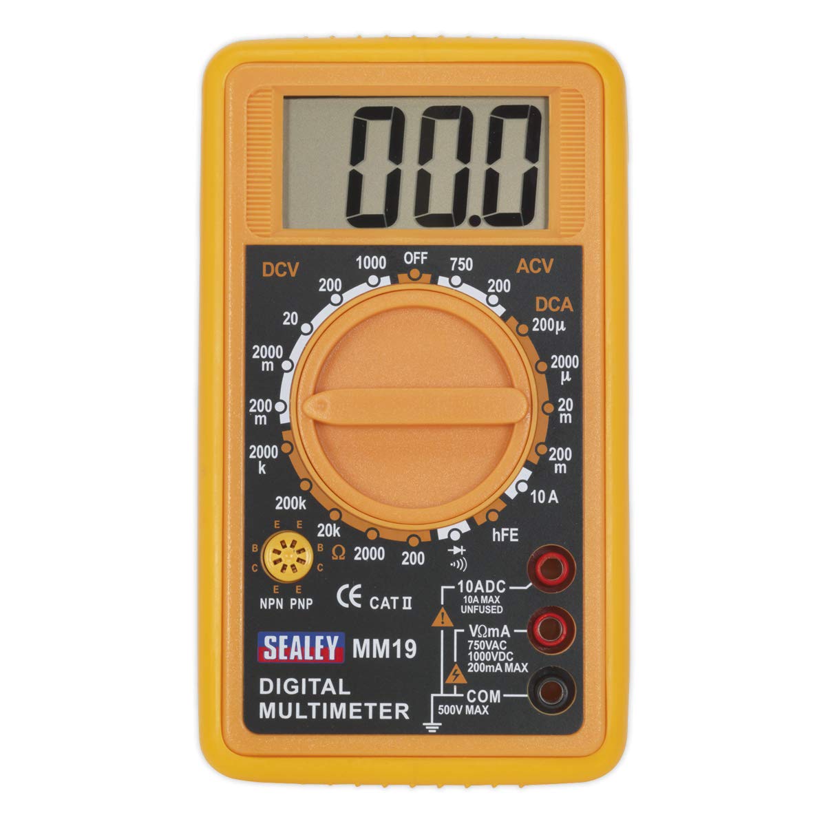
The Sealey MM19 Digital Multimeter, shown with its yellow casing, large LCD display, rotary function switch, and red and black test leads connected to the input jacks.
Składniki:
- Wyświetlacz LCD: Large (46 x 25mm) digital display for reading measurements.
- Przełącznik obrotowy: Służy do wyboru żądanej funkcji pomiarowej i zakresu.
- VΩmA Input Jack: Dla voltage, resistance, and current measurements up to 200mA.
- 10ADC Input Jack: For high current measurements up to 10A DC (unfused).
- Gniazdo wejściowe COM: Wspólny (ujemny) sygnał wejściowy dla wszystkich pomiarów.
- Gniazdo hFE: For transistor (NPN/PNP) testing.
- Przewody testowe: Czerwony (dodatni) i czarny (ujemny) przewód do podłączania do obwodów.
4. Konfiguracja
4.1. Instalacja baterii
The Sealey MM19 Multimeter requires a 9V battery for operation. If the display does not illuminate or shows a low battery indicator, the battery needs to be installed or replaced.
- Upewnij się, że multimetr jest wyłączony.
- Znajdź pokrywę komory baterii z tyłu urządzenia.
- Remove the screw(s) securing the cover and carefully lift it off.
- Connect a new 9V battery to the battery clips, observing correct polarity.
- Umieść baterię w komorze i załóż pokrywę, zabezpieczając ją śrubą(-ami).
4.2. Podłączanie przewodów pomiarowych
The multimeter is supplied with a pair of test leads (red and black).
- Włóż czarny przewód pomiarowy do KOM Gniazdo wejściowe (wspólne).
- Dla większości pomiarów (objętośćtage, resistance, low current), insert the czerwony przewód pomiarowy do VΩmA gniazdo wejściowe.
- For high DC current measurements (up to 10A), insert the czerwony przewód pomiarowy do 10 ADC gniazdo wejściowe.
5. Instrukcja obsługi
To operate the multimeter, select the desired function and range using the rotary switch.
5.1. Pomiar objętości prądu stałegotage (prąd stały)
- Insert the red lead into the VΩmA jack and the black lead into the COM jack.
- Set the rotary switch to the desired DCV range (e.g., 200m, 2000m, 20, 200, 1000). Start with the highest range if the voltage jest nieznany.
- Podłącz przewody pomiarowe do mierzonego elementu lub obwodu.
- Przeczytaj tomtage wartość na wyświetlaczu LCD.
5.2. Pomiar objętości ACtage (ACV)
- Insert the red lead into the VΩmA jack and the black lead into the COM jack.
- Set the rotary switch to the desired ACV range (e.g., 200, 750). Start with the highest range if the voltage jest nieznany.
- Podłącz przewody pomiarowe do mierzonego elementu lub obwodu.
- Przeczytaj tomtage wartość na wyświetlaczu LCD.
5.3. Pomiar prądu stałego (DCA)
- For currents up to 200mA: Insert the red lead into the VΩmA jack and the black lead into the COM jack.
- Dla prądów do 10A: Insert the red lead into the 10ADC jack and the black lead into the COM jack.
- Set the rotary switch to the desired DCA range (e.g., 200μ, 2000μ, 20m, 200m, 10A). Start with the highest range if the current is unknown.
- Wyłącz zasilanie obwodu. Open the circuit where the current is to be measured.
- Podłącz multimetr szeregowo do obwodu.
- Podłącz zasilanie do obwodu i odczytaj wartość prądu na wyświetlaczu LCD.
5.4. Pomiar rezystancji (Ω)
- Insert the red lead into the VΩmA jack and the black lead into the COM jack.
- Set the rotary switch to the desired Resistance (Ω) range (e.g., 200, 2000, 20k, 200k, 2000k).
- Upewnij się, że testowany obwód jest odłączony od napięcia.
- Podłącz przewody pomiarowe do mierzonego elementu.
- Odczytaj wartość rezystancji na wyświetlaczu LCD.
5.5. Test ciągłości dźwięku
- Insert the red lead into the VΩmA jack and the black lead into the COM jack.
- Set the rotary switch to the continuity symbol (speaker icon).
- Upewnij się, że testowany obwód jest odłączony od napięcia.
- Podłącz przewody pomiarowe do elementu lub przewodu.
- If continuity exists (low resistance), the meter will emit an audible tone. The display will show the resistance value.
5.6. Diode/Transistor Verification Mode (hFE)
- Insert the red lead into the VΩmA jack and the black lead into the COM jack for diode testing.
- Set the rotary switch to the diode symbol.
- Podłącz czerwony przewód do anody, a czarny przewód do katody diody. Na wyświetlaczu pojawi się napięcie przewodzenia.tage drop. Reverse the leads; the display should show 'OL' (open loop) for a good diode.
- For transistor hFE measurement, insert the transistor leads (Emitter, Base, Collector) into the appropriate sockets (E, B, C) in the hFE test socket, ensuring correct NPN or PNP type selection.
- Odczytaj wartość hFE na wyświetlaczu LCD.
6. Konserwacja
6.1. Czyszczenie
Wytrzyj licznik casing z reklamąamp Ściereczką i łagodnym detergentem. Nie używaj środków ściernych ani rozpuszczalników. Przed użyciem upewnij się, że miernik jest całkowicie suchy.
6.2. Wymiana baterii
Refer to Section 4.1 for battery installation instructions. Replace the 9V battery when the low battery indicator appears on the display to maintain measurement accuracy.
7. Rozwiązywanie Problemów
- Brak wyświetlacza: Sprawdź instalację akumulatora i upewnij się, że jest on odpowiednio naładowany.
- 'OL' or '1' on Display: This usually indicates an over-range condition or an open circuit. Select a higher range or check connections.
- Nieprawidłowe odczyty: Ensure the correct function and range are selected. Check test lead connections and battery condition.
- Brak ciągłości tonu: Verify the circuit is de-energized and the leads are making good contact.
8. Specyfikacje
| Parametr | Wartość |
|---|---|
| Marka | Sealey |
| Numer modelu | MM19 |
| Źródło zasilania | Zasilanie bateryjne (9 V) |
| Wyświetlacz | Digital LCD (46 x 25mm) |
| Objętość DCtage (prąd stały) | 200mV, 2000mV, 20V, 200V, 1000V |
| AC Objętośćtage (ACV) | 200V, 750V |
| Prąd stały (DCA) | 200µA, 2000µA, 20mA, 200mA, 10A |
| Odporność (Ω) | 200Ω, 2000Ω, 20kΩ, 200kΩ, 2000kΩ |
| Ciągłość | Audible tone below approx. 30Ω |
| Test Diody | Przekaż tomtage drop display |
| Test tranzystora | hFE (NPN/PNP) |
| Ocena bezpieczeństwa | CE CAT II, IEC 1010 |
| Wymiary (dł. x szer. x wys.) | 1.93 x 4.21 x 6.06 cala |
| Waga przedmiotu | 9.5 uncji (0.27 kilograma) |
9. Gwarancja i wsparcie
For warranty information or technical support, please refer to the documentation provided with your purchase or contact Sealey customer service directly. Keep your proof of purchase for any warranty claims.


