1. Wprowadzenie
This manual provides detailed instructions for the safe and effective operation, setup, and maintenance of your Associated Equipment Model 6042 Digital Electrical System Tester. This device is designed for testing 12V and 24V electrical systems, including batteries, starters, and charging systems, with a capacity of up to 500 amps.
The Associated Equipment 6042 is engineered for high quality and versatility, featuring digital displays for precise readings and heavy-duty leads for reliable testing. It is proudly made in the USA.
2. Instrukcje bezpieczeństwa
Always prioritize safety when operating this equipment. Failure to follow these instructions may result in injury or damage to equipment.
- Always wear eye protection when working on an engine.
- Batteries produce explosive gases during normal operation. Do not smoke or allow flame or sparks near the battery or engine. Ensure adequate ventilation.
- Avoid fan belts and other hot or moving parts of the engine. Be aware that electric fans may start automatically.
- Engine exhaust contains carbon monoxide, a deadly poison. Operate vehicles only in a well-ventilated area.
- Do not connect or remove test clamps while a load is applied.
- Do not connect test clamps to the carburetor, fuel lines, or sheet metal parts of the frame. Connect to appropriate battery terminals or designated test points.
3. Cechy i komponenty produktu
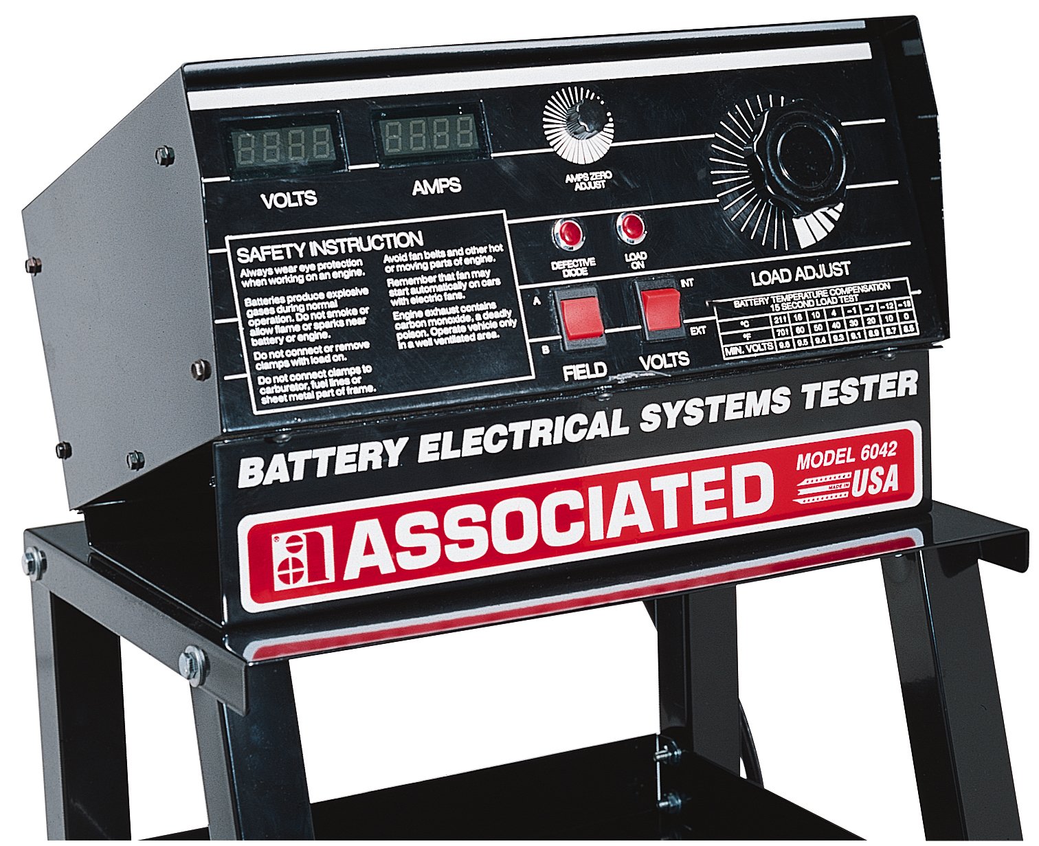
Rysunek 1: Associated Equipment Model 6042 Digital Electrical System Tester. This image displays the front panel with digital readouts for Volts and Amps, control knobs for Amps Zero Adjust and Load Adjust, indicator lights for Defective Diode and Load On, and connection points for Field and Volts. A table for Battery Temperature Compensation is also visible.
The Model 6042 features a robust design for professional use. Key components and features include:
- Digital Volts Display: Zapewnia precyzyjną objętośćtage odczyty.
- Cyfrowy AmpWyświetlacz: Shows positive and negative amperage for diagnosing current leakage.
- Amps Zero Adjust Knob: For calibrating the ampwyczyść wyświetlacz.
- Load Adjust Knob: Controls the load applied during testing.
- Defective Diode Indicator: Illuminates if a defective diode is detected.
- Load On Indicator: Shows when a load is being applied.
- Field/Volts Connections: Input terminals for various test configurations.
- Heavy-Duty Leads: Single extruded leads designed for testing up to 15 feet apart.
- Curved Discs: Unique design to prevent hot spots during load testing.
- Battery Temperature Compensation Table: Provides minimum voltage values for 15-second load tests based on battery temperature.
4. Konfiguracja i przygotowanie
- Rozpakowywanie: Carefully remove the tester from its packaging. Inspect for any shipping damage.
- Umieszczenie: Position the tester on a stable, level surface in a well-ventilated area, away from flammable materials.
- Źródło zasilania: The unit is battery-powered. Ensure the internal battery is charged or functioning correctly for accurate readings, especially for the amps probe.
- Inspekcja wstępna: Przed każdym użyciem należy sprawdzić wszystkie kable i połączenia pod kątem zużycia lub uszkodzeń.
5. Instrukcja obsługi
This section outlines general operating procedures. Refer to specific test procedures for detailed steps.
5.1. Podstawowe połączenie
- Upewnij się, że zapłon pojazdu jest wyłączony i wszystkie akcesoria są odłączone.
- Connect the positive (+) test clamp do dodatniego bieguna akumulatora.
- Connect the negative (-) test clamp to the negative battery terminal or a good chassis ground point, away from the battery.
- Ensure connections are secure before proceeding.
5.2. Amps Zero Adjustment
- Before applying any load, turn the "Amps Zero Adjust" knob until the digital Amps display reads "0.00". This calibrates the current sensor.
5.3. Tomtage Pomiar
- Once connected, the digital Volts display will show the current battery voltage.
5.4. Load Testing (Battery)
- With the tester connected and Amps zeroed, slowly turn the "Load Adjust" knob clockwise to apply a load to the battery.
- Observe the digital Volts and Amps displays. The "Load On" indicator will illuminate.
- Refer to the "Battery Temperature Compensation 15 Second Load Test" table on the unit for minimum acceptable voltage readings based on battery temperature.
- Apply the load for no more than 15 seconds to prevent battery damage or overheating of the tester.
- After 15 seconds, turn the "Load Adjust" knob counter-clockwise to remove the load.
- Compare the observed voltage under load with the values in the compensation table.
5.5. Alternator/Charging System Test
- Connect the tester as described in "5.1. Basic Connection".
- Uruchom silnik pojazdu.
- Observe the Volts display. A healthy charging system should show voltage typically between 13.5V and 14.5V.
- Ten Amps display can indicate charging current. Positive amps indicate current flowing into the battery, while negative amps could indicate a discharge or parasitic draw.
- If the "Defective Diode" indicator illuminates, it suggests a potential issue with the alternator's rectifier diodes.
5.6. Battery Temperature Compensation Table
This table provides the minimum acceptable voltage for a 15-second load test at various battery temperatures.
| Temperatura | 21°C (70°F) | 18°C (65°F) | 10°C (50°F) | 4°C (40°F) | -1°C (30°F) | -7°C (20°F) | -12°C (10°F) | -18°C (0°F) |
|---|---|---|---|---|---|---|---|---|
| Min. Volts | 9.6 | 9.5 | 9.4 | 9.3 | 9.1 | 8.9 | 8.7 | 8.5 |
6. Konserwacja i pielęgnacja
- Czyszczenie: Przetrzyj urządzenie miękką, suchą ściereczką. Nie używaj środków czyszczących o właściwościach ściernych ani rozpuszczalników.
- Składowanie: Store the tester in a clean, dry environment when not in use. Protect it from extreme temperatures and direct sunlight.
- Kontrola kabla: Regularly inspect test leads and clamps for cuts, cracks, or corrosion. Replace damaged components immediately.
- Bateria wewnętrzna: Ten amps probe is battery operated. Ensure its battery is maintained and replaced as needed for accurate readings.
7. Rozwiązywanie Problemów
| Problem | Możliwa przyczyna | Rozwiązanie |
|---|---|---|
| Brak wyświetlacza lub nieprawidłowe odczyty | Loose connections, discharged internal battery (for amps probe), damaged leads. | Check all connections. Ensure the amps probe battery is functional. Inspect and replace damaged leads. |
| Amps display not zeroing | Amps probe not calibrated, external magnetic interference. | Adjust the "Amps Zero Adjust" knob. Move the tester away from strong magnetic fields. |
| "Defective Diode" indicator illuminates | Faulty alternator rectifier diodes. | Further diagnosis of the alternator is required. Consult a qualified technician. |
| Tester gets hot during load test | Excessive load duration, insufficient cooling. | Limit load tests to 15 seconds. Allow the unit to cool between tests. Ensure proper ventilation. |
8. Specyfikacje
| Funkcja | Specyfikacja |
|---|---|
| Numer modelu | 6042 |
| Tomtage Kompatybilność | 12V / 24V |
| Maksymalnie Ampwymazać | 500 Amps |
| Typ pomiaru | Amperomierz, woltomierz |
| Źródło zasilania | Zasilany bateryjnie |
| Waga przedmiotu | 48 funta (ok. 21.77 kg) |
| Wymiary produktu (dł. x szer. x wys.) | 19 x 36 x 8 cala (ok. 48.26 x 91.44 x 20.32 cm) |
| UPC | 099684000505, 099684003605 |
| Producent | Powiązany sprzęt |
| Kraj pochodzenia | USA |
9. Gwarancja i wsparcie
For warranty information or technical support, please refer to the documentation included with your purchase or contact Associated Equipment directly. This product is proudly made in the USA, reflecting a commitment to quality and durability.


