1. Wprowadzenie
The Channel Vision C-0214 is a versatile service module designed to integrate both telephone and RF (Radio Frequency) signals within a structured wiring system. This module provides distribution for up to six telephone outlets, each supporting up to four lines, and includes a 4-way RF splitter for CATV distribution. It is compliant with TIA/EIA-568A and TIA 570 standards and is compatible with CAT 5e cabling.
This manual provides detailed instructions for the proper installation, operation, and maintenance of your C-0214 module.
2. Koniec produktuview i komponenty
The C-0214 module features a combination of RJ45 jacks for telephone connections and F-type coaxial connectors for RF signals. Understanding the layout of these connectors is crucial for correct installation.
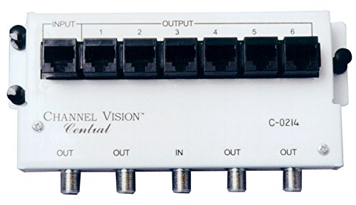
Rysunek 1: Przód view of the Channel Vision C-0214 module. The top row features one RJ45 INPUT port and six RJ45 OUTPUT ports (labeled 1 through 6) for telephone connections. The bottom row includes F-type coaxial connectors: three OUT ports, one IN port, and two additional OUT ports for RF/CATV distribution.
- Wejście RJ45: Single port for incoming telephone lines.
- RJ45 Outputs (1-6): Six ports for distributing telephone lines to various outlets.
- Wejście RF: Single F-type coaxial port for incoming CATV/RF signal.
- WYJŚCIE RF: Five F-type coaxial ports for distributing CATV/RF signal to various locations.
3. Konfiguracja i instalacja
Before beginning installation, ensure all power to the structured wiring enclosure is disconnected. It is recommended to have a qualified technician perform the installation.
3.1. Mounting the Module
- Position the C-0214 module within your structured wiring enclosure.
- Secure the module using appropriate mounting hardware (screws or clips) provided with your enclosure.
3.2. Telephone Wiring
The C-0214 supports up to 6 telephone outlets, each capable of handling up to 4 lines. It is TIA/EIA-568A and TIA 570 compliant and CAT 5e compatible.
- Connect the incoming telephone line(s) from your service provider to the single RJ45 port labeled "INPUT" on the module.
- Connect CAT 5e or higher rated cables from your wall outlets to the RJ45 ports labeled "OUTPUT 1" through "OUTPUT 6" on the module. Ensure proper wiring according to TIA/EIA-568A or TIA 570 standards.
3.3. RF/CATV Wiring
The module includes a 4-way RF splitter for distributing broadband signals from 5MHz to 1000MHz. All RF ports are DC and IR passing.
- Connect the incoming CATV/RF signal from your service provider to the F-type coaxial port labeled "IN" on the module.
- Connect coaxial cables from your wall outlets to the F-type coaxial ports labeled "OUT" on the module.
4. Instrukcja obsługi
Once properly installed, the C-0214 module operates passively to distribute telephone and RF signals.
4.1. Telephone Distribution
The module automatically routes the incoming telephone lines to all connected output ports. Any telephone device connected to a wall outlet wired to the module will receive the telephone service.
4.2. RF/CATV Distribution
The integrated 4-way splitter distributes the incoming RF signal to all connected output ports. Devices such as televisions or cable modems connected to wall outlets wired to the module will receive the CATV/broadband signal.
5. Konserwacja
The Channel Vision C-0214 module is designed for maintenance-free operation. No user-serviceable parts are inside.
- Keep the module and its connections free from dust and moisture.
- Upewnij się, że wszystkie połączenia kablowe są bezpieczne.
- Do not attempt to open or repair the module.
6. Rozwiązywanie Problemów
If you experience issues with your C-0214 module, review następujące typowe problemy i rozwiązania:
- No Dial Tone on Telephone Outlets:
- Verify the incoming telephone line is active and properly connected to the RJ45 INPUT port.
- Check all RJ45 output connections for proper seating and wiring.
- Ensure the telephone device is functioning correctly by testing it directly at the incoming line if possible.
- No CATV/RF Signal:
- Verify the incoming CATV/RF signal is active and properly connected to the F-type coaxial IN port.
- Check all F-type coaxial output connections for proper seating and tightness.
- Ensure the receiving device (TV, modem) is functioning correctly.
- Poor Signal Quality (RF):
- Ensure all coaxial connections are tight and free from damage.
- Check for excessive cable length or poor quality cabling, which can degrade signal.
If problems persist after attempting these solutions, contact Channel Vision customer support.
7. Specyfikacje
| Funkcja | Opis |
|---|---|
| Numer modelu | C-0214 |
| Marka | Wizja kanału |
| Telephone Ports | 1 RJ45 Input, 6 RJ45 Outputs |
| Telephone Lines Supported | Up to 4 lines per outlet |
| Telephone Standards | TIA/EIA-568A, TIA 570 compliant |
| Cable Compatibility (Telephone) | CAT 5e compatible |
| Rozdzielacz RF | 4-drożny |
| Zakres częstotliwości RF | 5 MHz - 1000 MHz |
| RF Port Features | All ports DC and IR passing |
| Wymiary (dł. x szer. x wys.) | 8.75 x 5.75 x 3.5 cala |
| Waga | 7.2 uncji |
8. Gwarancja i wsparcie
Channel Vision products are manufactured to high-quality standards. For specific warranty information, please refer to the warranty card included with your product or visit the official Channel Vision webZachowaj dowód zakupu na wypadek roszczeń gwarancyjnych.
For technical support or service inquiries, please contact Channel Vision customer service directly. Contact information can typically be found on the manufacturer's webwitryny lub opakowania produktu.


