
1. Wprowadzenie
This manual provides instructions for the DORHEA DC-DC Buck Boost Converter Module, model DAD12748-1. This versatile module functions as an adjustable step-up/down voltage regulator, capable of both boosting and bucking input voltage to achieve a desired output. It features an integrated LCD digital voltmeter and ammeter for real-time monitoring of input/output voltage, current, and power. Designed for various applications requiring precise voltage and current control, this module offers stable and reliable performance.
2. Informacje dotyczące bezpieczeństwa
WARNING: Electrical Shock Hazard. Improper use can result in serious injury or death.
- Always ensure power is disconnected before making any connections or adjustments to the module.
- Nie przekraczaj określonej objętości wejściowejtage, objętość wyjściowatage, or current limits.
- Ensure proper heat dissipation, especially when operating at higher currents or power levels.
- Avoid short circuits. Although the module has short-circuit protection, repeated or prolonged short circuits can damage the device.
- Keep the module away from moisture, dust, and extreme temperatures.
- This module is intended for use by individuals with adequate knowledge of electronics and electrical safety.
3. Koniec produktuview
The DORHEA DC-DC Buck Boost Converter Module is built with a boost and buck chip as the main controller, external 60V 75A MOS tube, and double 60V 5A SS56 Schottky rectifiers for enhanced stability. It features an LCD display for clear readings and user-friendly buttons for control.
Główne cechy:
- Adjustable input voltagZakres: DC 5.5-30 V
- Regulowana moc wyjściowatagZakres: DC 0.5-30 V
- Adjustable output current: 0-4A (with enhanced heat dissipation)
- Maximum output power: 35W (50W with enhanced heat dissipation)
- Integrated LCD display for voltage, current, and power monitoring
- Button controls for display switching and output ON/OFF
- Tomtage display resolution: 0.05V
- Current display resolution: 0.005A
- Safety protections: Soft Start, Input Reverse Protection, Output Anti-Backflow, Short Circuit Protection, Low-Voltage Ochrona
Identyfikacja komponentu:
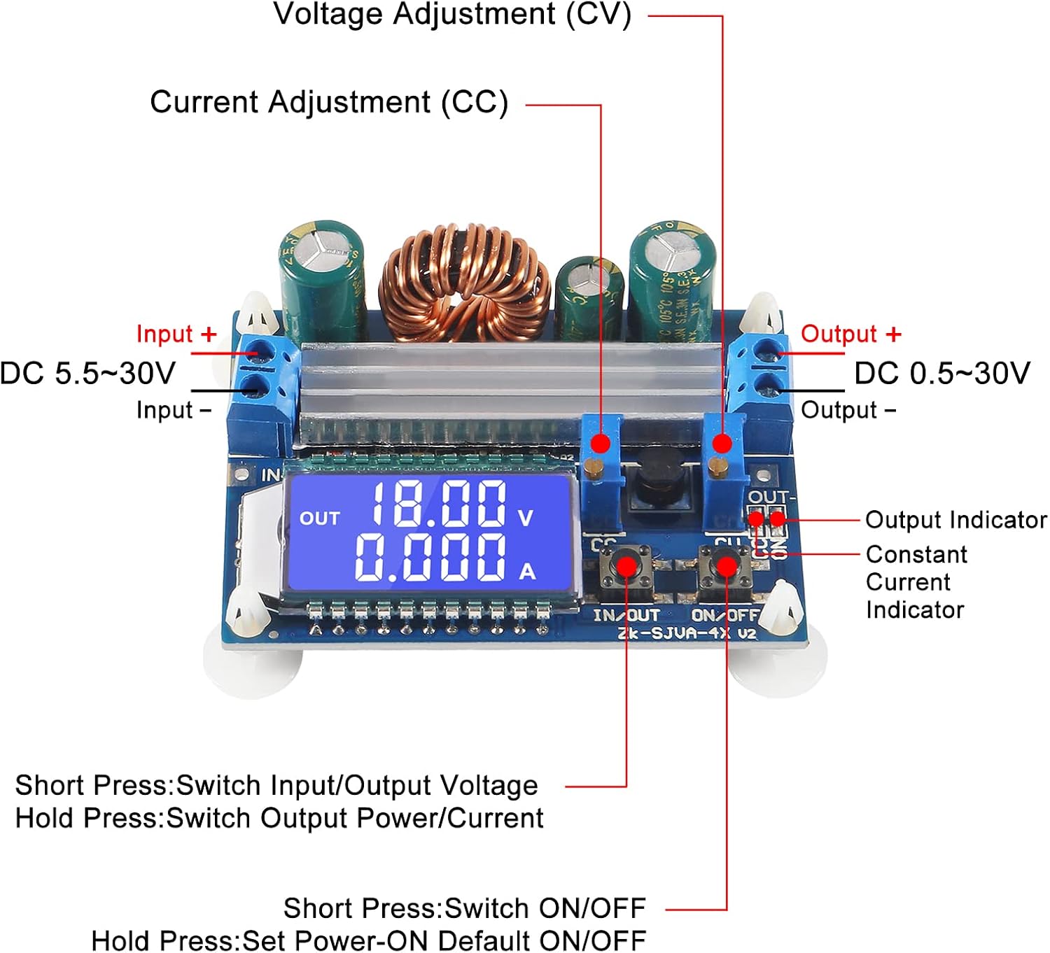
Figure 3.1: Labeled diagram of the module's main components.
This image illustrates the key connection points and controls on the module. Observe the "Input +" and "Input -" terminals for power input, and "Output +" and "Output -" for power output. The "CV" (Constant Voltage) and "CC" (Constant Current) potentiometers are used for adjustment. The "IN/OUT" and "ON/OFF" buttons control display and output respectively. The LCD screen displays operational parameters.

Rycina 3.2: Przód view of the module with LCD display.
Ten view provides a clear look at the module's front, highlighting the LCD display which shows the output voltage and current. The input and output terminals are visible on the left and right sides, respectively. The two control buttons are located below the LCD screen.
4. Specyfikacje
| Parametr | Wartość |
|---|---|
| Wejście Voltage Zakres | DC 5.5V - 30V (Note: Input voltage below 4.7V triggers low-voltagochrona) |
| Objętość wyjściatage Zakres | DC 0.5V - 30V (Adjustable) |
| Prąd wyjściowy | 3A (stable long-term), up to 4A (with enhanced heat dissipation) |
| Moc wyjściowa | 35W (natural heat dissipation), up to 50W (with enhanced heat dissipation) |
| Tomtage Rozdzielczość wyświetlacza | 0.05 V |
| Aktualna rozdzielczość wyświetlacza | 0.005A |
| Efektywność transferu | Około. 88% |
| Częstotliwość pracy | 180KHz |
| Wymiary (dł. x szer. x wys.) | 66mm x 48mm x 21mm |
| Średnica otworu montażowego | 4mm |
| Łagodny start | Yes (Note: High power load module may fail when started without soft start) |
| Ochrona przed odwrotnym wejściem | Tak |
| Output Anti-Backflow | Yes (No additional anti-backflow diode required for battery charging) |
| Zabezpieczenie przed zwarciem | Yes (Module automatically shuts down output, restored after re-energizing) |
| Niska objętośćtage Ochrona | Default approx. 4.7V (Output disconnected if input is less than 4.7V) |
5. Konfiguracja
Follow these steps to set up your DC-DC Buck Boost Converter Module:
- Przygotuj połączenia: Ensure all power sources are disconnected before making any wiring.
- Połączenie wejściowe: Connect your DC power source to the "Input +" and "Input -" terminals. Observe polarity: positive to "Input +" and negative to "Input -". The module has input reverse protection, but correct connection is always recommended.
- Połączenie wyjściowe: Connect your load or device to the "Output +" and "Output -" terminals. Observe polarity: positive to "Output +" and negative to "Output -".
- Początkowe uruchomienie: Once all connections are secure, apply power to the input terminals. The LCD display should illuminate, showing the current input or output voltage.
- Rozpraszanie ciepła: For continuous operation at higher currents (above 3A) or power (above 35W), ensure adequate heat dissipation. This may involve attaching the included heatsink or providing active cooling.

Figure 5.1: Module with heatsink for enhanced heat dissipation.
This image shows the module alongside an aluminum heatsink. For operations requiring higher current or power, attaching this heatsink to the main power components on the module is recommended to prevent overheating and ensure stable performance.
6. Instrukcja obsługi
The module features two buttons and two potentiometers for control and adjustment.
Funkcje przycisków:
- Przycisk wejścia/wyjścia:
- Krótkie naciśnięcie: Switches the LCD display between input voltage i wyjście voltage.
- Długie naciśnięcie: Switches the LCD display between output current and output power.
- Przycisk WŁ./WYŁ.:
- Krótkie naciśnięcie: Toggles the output ON or OFF.
- Długie naciśnięcie: Sets the default output state (ON or OFF) for the next power-up. The setting is saved.
Potentiometer Adjustments:

Figure 6.1: Close-up of adjustment potentiometers and LCD.
Na tym obrazie przedstawiono szczegółowo view of the two potentiometers, labeled "CV" and "CC", located near the output terminals. These are used for fine-tuning the output voltage i aktualne limity.
- CV (stała objętośćtage) Potentiometer:
- Rotate clockwise to increase the output voltage.
- Rotate counter-clockwise to decrease the output voltage.
- Adjust this to set your desired output voltage.
- CC (Constant Current) Potentiometer:
- Rotate clockwise to increase the current limit.
- Rotate counter-clockwise to decrease the current limit.
- When the load current reaches the set current, the module enters constant current (CC) mode, and the red "CC" indicator light will illuminate. This protects the load and the module from overcurrent.
Ważny: Always adjust the CV potentiometer first to set the desired voltage, then adjust the CC potentiometer to set the maximum current limit for your application. If charging a battery, set the voltage slightly higher than the battery's full charge voltage and the current to the desired charging current. The module will automatically switch to constant voltage mode when the battery is nearly full.
7. Konserwacja
- Czyszczenie: Keep the module clean and free from dust. Use a soft, dry cloth to wipe the surface. Do not use liquids or abrasive cleaners.
- Rozpraszanie ciepła: Regularly check that the heatsink (if installed) is free from dust and debris to ensure efficient cooling. Ensure adequate airflow around the module, especially during high-power operation.
- Znajomości: Okresowo sprawdzaj wszystkie połączenia przewodów, aby mieć pewność, że są solidne i nie są skorodowane.
- Składowanie: Gdy moduł nie jest używany, należy przechowywać go w suchym i chłodnym miejscu, z dala od bezpośredniego światła słonecznego i ekstremalnych temperatur.
8. Rozwiązywanie Problemów
| Problem | Możliwa przyczyna | Rozwiązanie |
|---|---|---|
| Brak wyświetlacza/brak wyjścia | No input power, incorrect wiring, input voltage za niskie. | Check input power supply. Verify input wiring polarity. Ensure input voltage is within 5.5V-30V range. Check if low-voltage protection is active (input below 4.7V). |
| Output shuts down unexpectedly | Short circuit, overcurrent, low-voltagOchrona została uruchomiona. | Check for short circuits in the output. Reduce load to stay within current limits. Re-energize the module after clearing a short circuit. Ensure input voltage is stable and above 4.7V. |
| Objętość wyjściowatage/current cannot be adjusted | Potentiometers at limit, faulty potentiometer. | Rotate potentiometers fully in both directions to check range. Ensure the module is powered on and not in a protection state. |
| Niedokładna objtage/bieżące odczyty | Objętość wejściowatage too low (for input measurement), calibration issue. | Zapewnij objętość wejściowątage is above 5V for accurate input measurement. If persistent, compare with an external multimeter. |
| Module gets hot during operation | Operating at high current/power without sufficient heat dissipation. | Install the provided heatsink. Ensure adequate airflow. Reduce load if necessary. |
| High power load module may fail when started | Sudden high current draw during startup. | The module has a soft start feature. If issues persist with very high inductive or capacitive loads, consider adding an external soft-start circuit or gradually increasing ładunek. |
9. Gwarancja i wsparcie
For warranty information and technical support, please refer to the product's purchase documentation or contact the seller/manufacturer directly. Keep your purchase receipt as proof of purchase.
Producent: DORHEA
Numer modelu: DAD12748-1