
1. Wprowadzenie
The WALFRONT REX C100 is a high-precision PID temperature controller designed for various industrial and commercial applications. It utilizes advanced self-tuning PID technology to ensure rapid temperature adjustments with minimal overshoot, providing accurate and stable temperature control. This manual provides essential information for the safe and efficient operation of your REX C100 controller.
Key applications include food processing, chemical industries, injection molding, and other environments requiring precise thermal monitoring and control.
2. Informacje dotyczące bezpieczeństwa
- Zagrożenie elektryczne: Always disconnect power before installation, wiring, or maintenance to prevent electric shock.
- Prawidłowe okablowanie: Ensure all wiring connections are secure and comply with local electrical codes. Incorrect wiring can cause damage to the device or pose a fire hazard.
- Warunki środowiskowe: Operate the controller within the specified temperature and humidity ranges. Avoid exposure to corrosive gases, excessive dust, or moisture.
- Wykwalifikowany personel: Installation and wiring should only be performed by qualified personnel.
- Przeznaczenie: Use the device only for its intended purpose as a temperature controller. Do not modify the device.
3. Zawartość opakowania
Sprawdź, czy w opakowaniu znajdują się wszystkie elementy:
- 1 x WALFRONT REX C100 PID Temperature Controller
4. Koniec produktuview
The REX C100 features a clear digital display and intuitive controls for easy operation.

Rysunek 4.1: Przód kątowy View of REX C100 Controller. This image displays the front panel of the REX C100 PID Temperature Controller from an angled perspective. It clearly shows the dual digital displays for Process Value (PV) and Set Value (SV), along with indicator lights for ALM1, ALM2, OUT1, and AT. The 'SET' button and arrow keys are visible at the bottom left.
Opis panelu przedniego
- PV Display (Upper): Pokazuje aktualną wartość procesu (zmierzoną temperaturę).
- SV Display (Lower): Shows the Set Value (target temperature).
- ALM1 Indicator: Świeci się, gdy alarm 1 jest aktywny.
- ALM2 Indicator: Świeci się, gdy alarm 2 jest aktywny.
- OUT1 Indicator: Świeci się, gdy wyjście sterujące jest aktywne.
- Wskaźnik AT: Illuminates during auto-tuning (self-tuning PID).
- Przycisk SET: Służy do wejścia w tryb ustawiania parametrów i potwierdzania wyborów.
- Arrow Buttons (Up/Down/Left): Służy do poruszania się po menu i dostosowywania wartości.
Rear Panel and Terminals
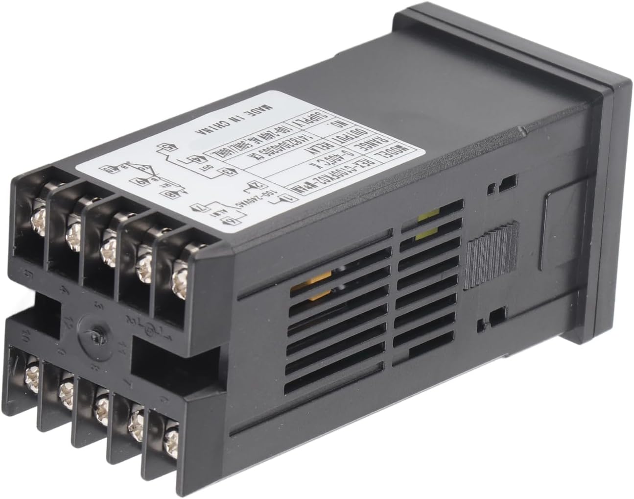
Rysunek 4.2: Tył View with Wiring Terminals. This image shows the back of the REX C100 controller, highlighting the screw terminals for electrical connections and the product label with specifications and a basic wiring diagram.
The rear panel contains the screw terminals for power input, sensor input, and control outputs. Refer to the wiring diagram on the device label for precise connections.
5. Konfiguracja
5.1 Montaż
The REX C100 is designed for panel mounting. Cut an appropriate opening in your control panel according to the device dimensions. Insert the controller into the opening and secure it using the provided mounting brackets from the rear.

Rysunek 5.1: REX C100 with Mounting Bracket. This image shows the REX C100 controller with its black plastic mounting bracket, illustrating how the device is secured into a panel cutout.
5.2 Okablowanie
WARNING: Ensure power is disconnected before performing any wiring.
Refer to the wiring diagram printed on the side label of the controller for accurate connections. A typical wiring configuration is as follows:

Rysunek 5.2: Wiring Diagram on Product Label. This image provides a close-up of the REX C100's side label, which includes a comprehensive wiring diagram for power, sensor input, and output connections.
- Power Supply (Terminals 1 & 2): Connect your 100-240VAC, 50/60Hz power source here.
- Output (OUT1) (Terminals 3, 4, 5): These are relay contacts. Connect your heating or cooling element through these terminals. The diagram shows Normally Open (NO) and Common (COM) connections.
- Alarm 1 (ALM1) (Terminals 6 & 7): Connect external alarm devices here.
- Alarm 2 (ALM2) (Terminals 8 & 9): Connect external alarm devices here.
- Sensor Input (Terminals 10 & 11): Connect your K-type thermocouple here. Ensure correct polarity for accurate readings.
After wiring, double-check all connections before applying power.
6. Instrukcja obsługi
6.1 Włączanie
Once wired correctly, apply power to the controller. The PV display will show the current temperature measured by the thermocouple, and the SV display will show the set target temperature.
6.2 Ustawianie temperatury docelowej (SV)
- Naciśnij USTAWIĆ Naciśnij przycisk raz. Wyświetlacz SV zacznie migać.
- Użyj Up I W dół arrow buttons to adjust the target temperature. The Lewy arrow button can be used to shift the cursor for faster adjustment of individual digits.
- Naciśnij USTAWIĆ button again to confirm the new SV. The display will stop flashing, and the controller will begin to regulate the temperature to the new set point.
6.3 PID Auto-Tuning
The REX C100 features an expert self-tuning PID function. Auto-tuning helps the controller learn the characteristics of your specific heating/cooling system to optimize control performance and minimize overshoot or undershoot.
To initiate auto-tuning:
- Ensure the system is at a stable temperature, preferably near your desired set point.
- Naciśnij i przytrzymaj USTAWIĆ button for approximately 3-5 seconds until the controller enters the parameter setting menu.
- Navigate through the parameters (using arrow keys) until you find the auto-tuning parameter (often labeled 'AT' or similar).
- Set the auto-tuning parameter to '1' (or 'ON') and confirm with the USTAWIĆ button. The 'AT' indicator light on the front panel will illuminate.
- The controller will cycle the output to determine the optimal PID parameters. This process may take some time (e.g., several heating/cooling cycles).
- Once auto-tuning is complete, the 'AT' indicator will turn off, and the controller will operate with the newly optimized PID parameters.
Note: Specific parameter codes and navigation may vary slightly. Refer to the detailed programming manual (if available) for advanced settings.
6.4 Ustawienia alarmu
The REX C100 includes two alarm outputs (ALM1, ALM2). These can be configured for various alarm types (e.g., high limit, low limit, deviation) and hysteresis. Access these settings through the parameter menu by pressing and holding the USTAWIĆ przycisk.
7. Konserwacja
- Czyszczenie: Clean the front panel with a soft, dry cloth. Do not use abrasive cleaners or solvents.
- Kontrola środowiskowa: Periodically inspect the operating environment to ensure it remains free of corrosive gases, excessive dust, and moisture.
- Kontrola połączenia: Occasionally check wiring connections for tightness, especially in environments with vibration.
- Kontrola czujnika: Inspect the thermocouple for any signs of damage or corrosion that could affect accuracy.
8. Rozwiązywanie Problemów
| Problem | Możliwa przyczyna | Rozwiązanie |
|---|---|---|
| Kontroler nie włącza się. | Brak zasilania, nieprawidłowe okablowanie. | Sprawdź połączenia zasilania (zaciski 1 i 2). Upewnij się, że napięcietage mieści się w zakresie 100–240 V AC. |
| PV display shows 'HHHH' or 'LLLL'. | Thermocouple open circuit or reverse connection. | Check thermocouple wiring (Terminals 10 & 11) for breaks or incorrect polarity. Ensure it is a K-type thermocouple. |
| Odczyt temperatury jest niedokładny. | Incorrect sensor type selected (if configurable); sensor fault; environmental interference. | Verify sensor type. Check sensor for damage. Ensure proper shielding if in an electrically noisy environment. |
| Output (OUT1) not activating. | SV not reached; output parameter incorrect; wiring issue. | Check SV. Verify output control mode. Inspect output wiring (Terminals 3, 4, 5). |
| Temperature overshoots/undershoots target. | Parametry PID nie zostały zoptymalizowane. | Perform PID auto-tuning (refer to Section 6.3). |
9. Specyfikacje
| Funkcja | Specyfikacja |
|---|---|
| Model | REX-C100 |
| Typ sterowania | Temperatura |
| Tryb sterowania | RELAY (Output) |
| Obiekty pomiarowe | All objects (with compatible K-type thermocouple) |
| Błąd pomiaru temperatury | ±1% (℃) |
| Objętość roboczatage | 100-240 V AC |
| Dokładność pomiaru | ±0.5% pełnej skali |
| Rezolucja | 14-bitowy |
| Wytrzymałość izolacji | 1500VAC/1 minuta |
| Waga | 164 g (ok. 6 uncji) |
| Temperature Range (K-Type) | 0-400°C (32-752°F) |
| Środowisko operacyjne | 0-50℃ (32-122°F), 30-85% RH, free of corrosive gas |
| Wymiary opakowania | 5.51 x 2.76 x 2.36 cala |
10. Gwarancja i wsparcie
Ten produkt jest objęty standardową gwarancją producenta na wady materiałowe i wykonawcze. Szczegółowe warunki i okres obowiązywania gwarancji znajdują się w dokumentacji zakupu.
W celu uzyskania wsparcia technicznego, pomocy w rozwiązywaniu problemów lub zgłoszenia reklamacji prosimy o kontakt bezpośrednio ze sprzedawcą lub producentem. Zachowaj paragon jako dowód zakupu.