
1. Wprowadzenie
This manual provides detailed instructions for the installation, operation, and maintenance of your ASHATA Prime B365M D2VX SI motherboard. This M-ATX motherboard supports 9th and 8th Generation Intel Core i9, i7, i5, i3, Pentium, and Celeron series processors with an LGA 1151 socket. It features integrated Gigabit Ethernet for network connectivity and an ALC887 7.1 channel sound chip for audio. Please read this manual thoroughly before proceeding with installation.

Rysunek 1.1: ASHATA Prime B365M D2VX SI Motherboard. This image displays the overall layout of the motherboard, highlighting the LGA 1151 socket, DDR4 memory slots, and various connectors. It supports 9th and 8th Gen Intel CPUs, features integrated Gigabit LAN, and an ALC887 7.1 channel sound chip.
2. Konfiguracja i instalacja
2.1 Instalacja procesora
Ensure the CPU socket lever is open. Carefully align your LGA 1151 processor with the socket, matching the triangular markers on the CPU and socket. Gently place the CPU into the socket without forcing it. Close the lever to secure the CPU.
2.2 Instalacja pamięci (RAM)
This motherboard features two DDR4 DIMM slots, supporting dual-channel DDR4 2666/2400/2133MHz memory modules up to a maximum capacity of 32GB. Open the clips on both ends of the DIMM slot. Align the memory module with the slot, ensuring the notch on the module matches the key in the slot. Press down firmly on both ends of the module until the clips snap into place.

Rysunek 2.1: Double Channel DDR4 Memory Slots. This image highlights the two DDR4 memory slots and the M.2 slot. The motherboard supports up to 32GB of DDR4 2666/2400/2133MHz memory and includes four Serial ATA III ports and one M.2 slot for storage.
2.3 Instalacja urządzenia pamięci masowej
The motherboard provides four Serial ATA III (SATA 6Gbps) interfaces for traditional hard drives and SSDs, and one M.2 slot for high-speed NVMe or SATA M.2 SSDs. Connect SATA data cables from your storage devices to the SATA ports on the motherboard. For M.2 SSDs, insert the module into the M.2 slot and secure it with the provided screw.
2.4 PCI Express Card Installation
The motherboard includes one PCI Express x16 graphics slot and two PCI Express x1 slots. Insert your graphics card or other expansion cards into the appropriate slots, ensuring they are fully seated and secured with the case's retention mechanism.
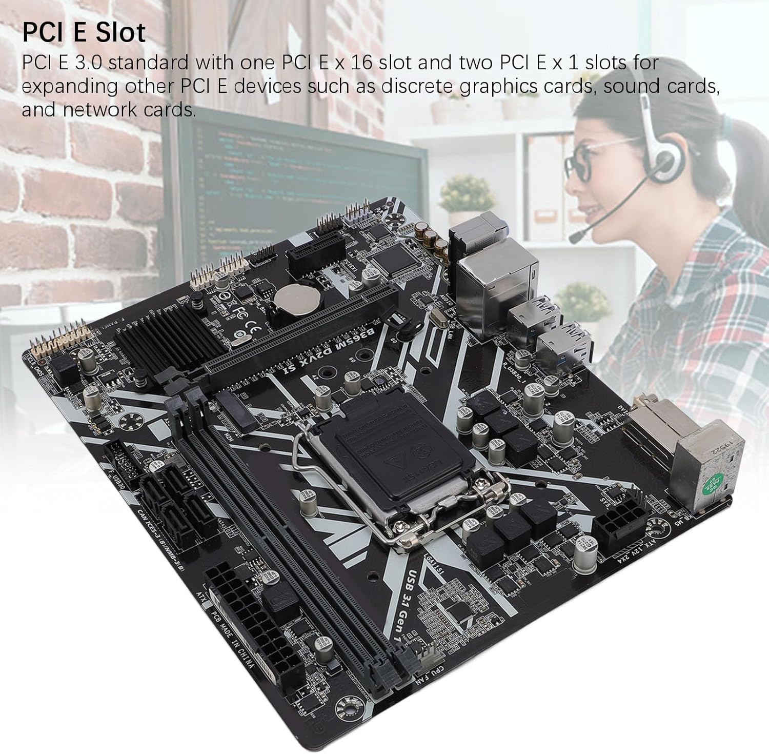
Rysunek 2.2: PCI E Slots. This image shows the PCI E 3.0 standard slots, including one PCI E x16 graphics slot and two PCI E x1 slots, allowing for expansion with discrete graphics cards, sound cards, and network cards.
2.5 Połączenia zasilania
Connect the 24-pin ATX main power connector and the 8-pin ATX 12V power connector from your power supply unit (PSU) to the corresponding ports on the motherboard. Ensure all power connections are secure.

Rysunek 2.3: Multi-Phase Power Supply Area. This image illustrates the robust construction of the motherboard, featuring all solid-state capacitors and 8-pin plus 24-pin power connectors for stable performance and long service life.
2.6 Połączenia peryferyjne
Connect your peripherals to the rear I/O panel. This includes USB 3.1 Gen 1 ports (4 on rear), USB 2.0 ports (2 on rear), the RJ-45 Ethernet port, and the 3 audio jacks. The motherboard also features a DVI interface for video output.

Rysunek 2.4: DVI Output and Rear I/O Ports. This image displays the rear I/O panel, highlighting the DVI output for connecting to a TV or display, along with USB ports, Ethernet, and audio jacks.
Wideo 2.1: Product Demonstration. This video provides a general overview and demonstration of a motherboard, showcasing its various components and features. While not specific to the B365M D2VX SI, it illustrates common motherboard aspects.
3. Instrukcja obsługi
3.1 Pierwsze uruchomienie
After assembling all components and connecting power, press the power button on your computer case. The system should initiate the boot process. If no display appears, refer to the troubleshooting section.
3.2 Dostęp do BIOS-u/UEFI
Aby uzyskać dostęp do narzędzia konfiguracji BIOS/UEFI, naciśnij wyznaczony klawisz (najczęściej USUNĄĆ or F2) repeatedly during the initial boot sequence. The BIOS/UEFI allows you to configure system settings, boot order, and monitor hardware status.
3.3 Wyjście wyświetlacza
Connect your monitor to the DVI port on the motherboard's rear I/O panel for integrated graphics output. If a discrete graphics card is installed, connect your monitor to the graphics card's output ports.
3.4 Network and Audio
The integrated Gigabit LAN provides high-speed network connectivity. Connect an Ethernet cable to the RJ-45 port. For audio, connect speakers or headphones to the appropriate audio jacks on the rear I/O panel. The ALC887 7.1 channel sound chip supports various audio configurations.
4. Konserwacja
Właściwa konserwacja zapewnia długowieczność i stabilną pracę płyty głównej.
- Czyszczenie: Regularly clean dust from inside your computer case using compressed air. Ensure the system is powered off and unplugged before cleaning. Avoid using liquids or abrasive materials.
- Elektryczność statyczna: Always discharge static electricity from your body before handling the motherboard or other components. Use an anti-static wrist strap if available.
- Aktualizacje BIOS-u: Okresowo sprawdzaj producenta webStrona z aktualizacjami BIOS/UEFI. Aktualizacje mogą poprawić kompatybilność, stabilność i wydajność. Postępuj zgodnie z instrukcjami aktualizacji, aby uniknąć uszkodzenia systemu.
- Warunki środowiskowe: Używaj płyty głównej w dobrze wentylowanym pomieszczeniu o stabilnej temperaturze i wilgotności, aby zapobiec przegrzaniu i degradacji podzespołów.
5. Rozwiązywanie Problemów
If you encounter issues, perform the following basic troubleshooting steps:
- Brak zasilania:
- Check if the power supply unit (PSU) is connected and switched on.
- Ensure the 24-pin and 8-pin power connectors are securely attached to the motherboard.
- Sprawdź, czy kabel przełącznika zasilania na panelu przednim jest prawidłowo podłączony do złącza płyty głównej.
- Brak wyświetlacza:
- Confirm the monitor is connected to the correct video output (motherboard DVI or discrete graphics card).
- Ponownie zamontuj kartę graficzną (jeśli dotyczy) i moduły pamięci.
- Jeśli to możliwe, przetestuj urządzenie przy użyciu innego monitora lub kabla.
- Niestabilność/awarie systemu:
- Sprawdź temperaturę procesora i procesora graficznego, aby mieć pewność, że mieści się ona w bezpiecznych granicach.
- Verify memory modules are properly seated and functioning correctly (test one module at a time).
- Upewnij się, że wszystkie sterowniki są aktualne.
- Network Not Detected:
- Ensure the Ethernet cable is securely connected to the RJ-45 port and the router/modem.
- Check network adapter drivers in the operating system.
- Verify network settings in the operating system.
- Brak dźwięku:
- Confirm speakers/headphones are connected to the correct audio jacks.
- Check audio drivers and sound settings in the operating system.
- Ensure the front panel audio connector is correctly attached to the motherboard header.
6. Specyfikacje
Below are the detailed specifications for the ASHATA Prime B365M D2VX SI motherboard:
| Funkcja | Specyfikacja |
|---|---|
| Model płyty głównej | B365M D2VX SI |
| Zestaw układów scalonych | Intel B365 High Speed Chipset |
| Gniazdo procesora | LGA 1151 |
| Supported CPU Types | 9th and 8th Generation Intel Core i9/i7/i5/i3, Pentium, Celeron Series Processors |
| Typ pamięci | 2 x gniazda DDR4 DIMM |
| Maksymalna pojemność pamięci | 32 GB |
| Memory Description | Supports Double Channel DDR4 2666/2400/2133MHz |
| PCI E Standard | PCI E 3.0 |
| PCI E Slots | 1 x PCI E X16 Graphics Slot, 2 x PCI E X1 Slots |
| Interfejsy pamięci masowej | 4 x Serial ATA III Interfaces, 1 x M.2 Slot |
| Interfejsy USB | 6 x USB 3.1 Gen 1 Ports (4 rear, 2 via header), 6 x USB 2.0/1.1 Ports (2 rear, 4 via header) |
| Interfejs wideo | 1 x DVI Interface |
| Układ audio | Integrated ALC887 7.1 Channel Sound Chip |
| Network Chip | Onboard Gigabit Network Chip |
| Złącza zasilania | 1 x 8 Pin Power Connector, 1 x 24 Pin Power Connector |
| Współczynnik kształtu płyty głównej | M-ATX |
| Wymiary paczki | Wymiary 29 x 26 x 6 cm |
| Waga przedmiotu | 568 gramów |
7. Gwarancja i wsparcie
For warranty information and technical support, please refer to the documentation included with your purchase or visit the official ASHATA website. Keep your proof of purchase for warranty claims. If you encounter issues not covered in this manual, contact ASHATA customer support for assistance.