1. Wprowadzenie
The GODIYMODULES SMC05 is an integrated stepper and servo motor driver controller designed for precise control of motor rotation, speed, and angle. Featuring a 1.8-inch color screen and intuitive knob operation, this module supports a wide range of applications requiring accurate motor positioning and speed regulation. It offers multiple control modes and communication options for versatile integration into various systems.
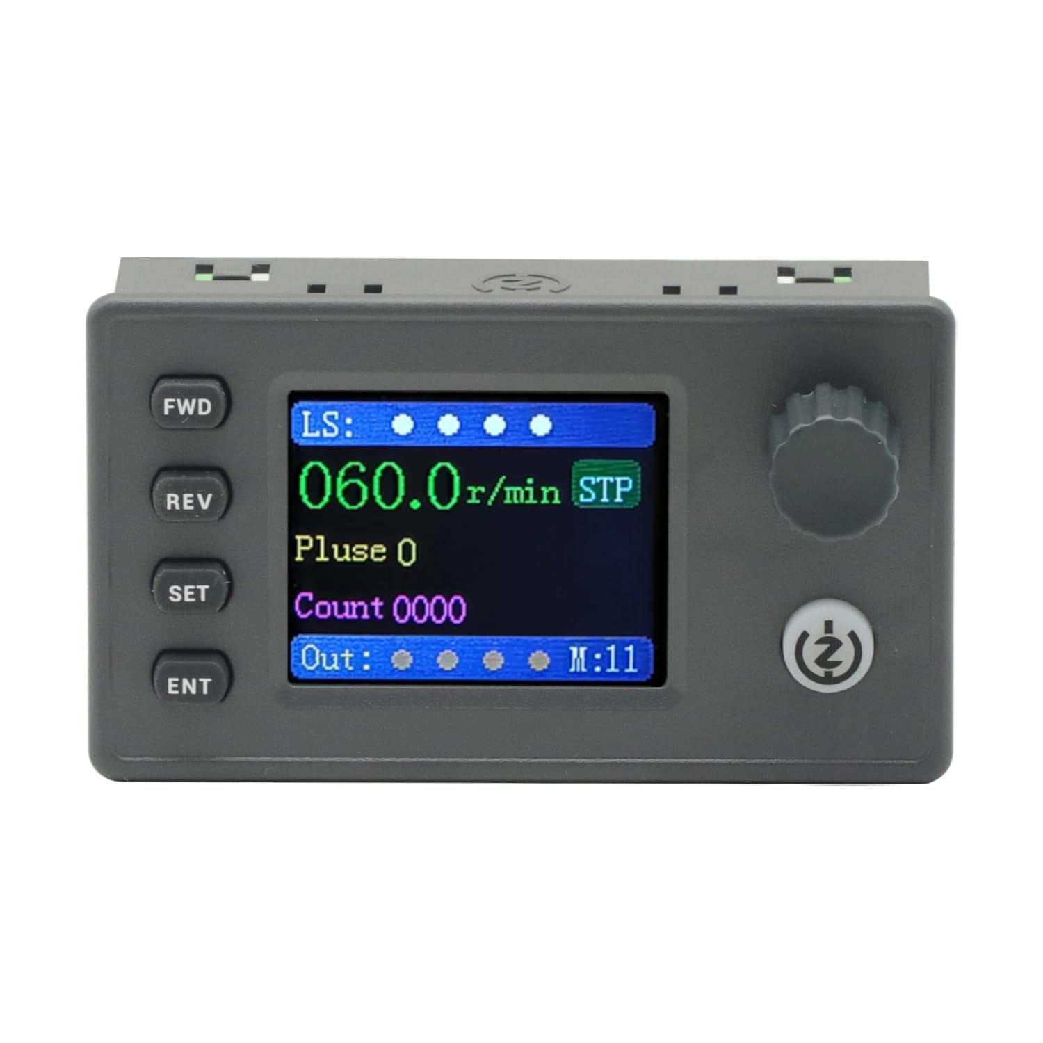
Figure 1: The SMC05 Stepper/Servo Motor Driver Controller, highlighting its 1.8-inch color screen, knob operation, and shortcut buttons.
2. Funkcje produktu
- Zintegrowane sterowanie: Combines stepper motor driver and servo motor control functionalities.
- Szeroki zakrestage Zakres: Operates with a working voltago napięciu 12-24 V.
- Kompaktowa konstrukcja: Product dimensions are 83x48x35.5mm.
- Sygnały wyjściowe: Features 4 output channels with 0V output voltage.
- Sygnały wejściowe: Includes 4 limit inputs and 3 extended key interfaces.
- High Pulse Frequency: Supports motor pulse frequencies from 1Hz to 200,000Hz.
- Wyświetlacz kolorowy: Equipped with a 1.8-inch color screen for clear information display.
- Puls objtage: Motor pulse voltage is 0V output, collector output form.
- Komunikacja: Supports Modbus protocol via serial port/485.
- Wiele trybów: Supports 20 different motion control modes.
- Obsługa języków: Display in both Chinese and English.

Figure 2: Key features of the SMC05 controller, including support for various modes and input/output capabilities.
3. Konfiguracja i instalacja
3.1 Zasilanie i połączenia
Upewnij się, że objętość roboczatage is within the specified range of 12-24V DC. Connect the power supply to the designated terminals. The controller features various input and output interfaces for connecting limit switches, expansion buttons, and motor drives.

Rysunek 3: Szczegółowy view of the SMC05 controller's extension interface, indicating connections for power, limit switches, expansion buttons, communication, and motor outputs.
3.2 Okablowanie silnika
Proper wiring of the stepper or servo motor drive is crucial for correct operation. Refer to the wiring diagrams provided to ensure all connections are secure and correctly aligned with the motor and power source.

Rysunek 4: Example wiring diagram for connecting the SMC05 controller to a microstep driver and a stepper motor.
4. Instrukcja obsługi
The SMC05 controller features a user-friendly interface with a 1.8-inch color screen, a rotary knob, and several control buttons for easy operation and parameter adjustment.
4.1 Panel sterowania ponadview

Figure 5: Front panel layout of the SMC05 controller with labels for all buttons, the rotary knob, and display indicators.
- FWD Button: Initiates forward rotation.
- Przycisk REV: Initiates reverse rotation.
- Przycisk SET: Enters the settings menu or exits current settings.
- Przycisk ENT: Potwierdza wybór lub przechodzi do podmenu.
- Pokrętło: Adjusts parameters such as speed, pulse count, and navigates menus.
- Przycisk Start/Stop: Starts or stops motor operation.
- Ekran wyświetlacza: Shows current speed, pulse count, motion mode, and various indicators.
4.2 Podstawowa obsługa
- Włączanie: Connect the 12-24V DC power supply. The screen will light up.
- Ustawienia parametrów: Naciśnij USTAWIĆ button to enter the settings menu. Use the rotary knob to navigate through options like Działanie, Silnik, I System. Naciskać laryngologia aby wybrać.
- Adjusting Speed/Pulse: W ramach Działanie or Silnik settings, you can adjust parameters such as forward pulse, forward speed, reverse pulse, and reverse speed using the rotary knob.
- Starting Motor: Once parameters are set, press the Uruchom/Zatrzymaj button to begin motor operation. The motor will rotate according to the configured speed and direction.
- Zmiana kierunku: Użyj Przód I OBRÓT SILNIKA buttons to change the motor's rotation direction during operation.
- Stopping Motor: Naciśnij Uruchom/Zatrzymaj button again to halt motor movement.
4.3 Advanced Features Demonstration
The following video demonstrates various operational aspects and advanced features of the SMC05 controller, including interface navigation, stepper motor control, use of expansion buttons, limit switches, and output control, as well as servo motor drive integration.
Video 1: Demonstration of the SMC05 controller's interface, stepper motor drive, expansion button functionality, limit switch activation, output control, and servo motor drive operation.
5. Specyfikacje
| Funkcja | Specyfikacja |
|---|---|
| Wymiary produktu | 3.27 x 1.89 x 1.4 cali (83 x 48 x 35.5 mm) |
| Waga przedmiotu | 3.27 uncji |
| Objętość roboczatage | 12-24V DC |
| Sygnał wyjściowy | 4 channels, 0V output voltage |
| Sygnał wejściowy | 4 limit inputs, 3 extended key interfaces |
| Motor Pulse Frequency | 1Hz - 200,000Hz |
| Typ wyświetlacza | 1.8-calowy kolorowy ekran |
| Motor Pulse Voltage | 0V output, collector output form |
| Protokół komunikacyjny | Modbus (serial port/485) |
| Zawarte komponenty | 1PCS SMC05 Controller |
6. Konserwacja
To ensure the longevity and optimal performance of your SMC05 controller, follow these maintenance guidelines:
- Utrzymuj urządzenie w czystości, bez kurzu i zanieczyszczeń. Do czyszczenia używaj miękkiej, suchej ściereczki.
- Unikaj wystawiania kontrolera na działanie ekstremalnych temperatur, wilgoci lub bezpośredniego światła słonecznego.
- Upewnij się, że wszystkie połączenia są solidne i nie mają śladów korozji. Regularnie sprawdzaj okablowanie pod kątem oznak zużycia lub uszkodzeń.
- Nie próbuj otwierać casing or modify the internal components, as this may void the warranty and cause damage.
7. Rozwiązywanie Problemów
If you encounter issues with your SMC05 controller, refer to the following common troubleshooting steps:
- Brak zasilania: Check the power supply connection and ensure it provides the correct voltage (12-24V DC). Verify the power adapter is functioning.
- Silnik nie porusza się:
- Ensure the motor is correctly wired to the driver and the driver to the controller.
- Check if the motor parameters (speed, pulse) are set correctly on the controller.
- Verify that the Start/Stop button has been pressed to initiate movement.
- Check for any active limit switch inputs that might be preventing movement.
- Incorrect Speed/Direction: Review the speed and direction settings in the controller's menu. Ensure the FWD/REV buttons are used appropriately.
- Problemy z wyświetlaniem: If the screen is blank or shows errors, try restarting the device. If the problem persists, contact support.
- Communication Errors (Modbus): Verify the serial port/485 connections and ensure the communication parameters (baud rate, parity, etc.) are correctly configured on both the controller and the connected device.
For persistent issues not resolved by these steps, please contact GODIYMODULES customer support.
8. Gwarancja i wsparcie
Information regarding specific warranty terms for the GODIYMODULES SMC05 controller is not available in the provided product data. Please refer to the product packaging or the manufacturer's official webStrona zawiera szczegółowe informacje o gwarancji.
For technical support, troubleshooting assistance, or inquiries about the product, please contact GODIYMODULES customer service through their official channels.