1. Wprowadzenie
This manual provides essential information for the safe and efficient operation of your Anern 4200W Hybrid Solar Inverter. Please read this manual thoroughly before installation and use. Keep it for future reference.
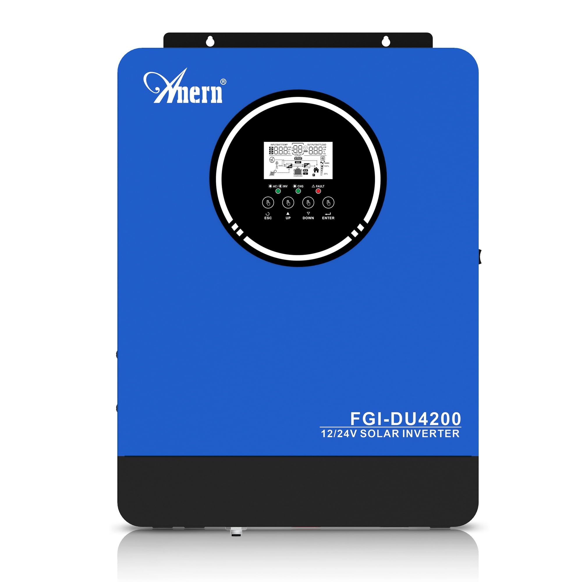
Figure 1: Anern 4200W Hybrid Solar Inverter. This image displays the main unit of the inverter, highlighting its key specifications such as 100A AC charging current, 4200W rated output power, and 500 VDC maximum PV array voltage.
2. Instrukcje bezpieczeństwa
Aby zmniejszyć ryzyko porażenia prądem, pożaru lub obrażeń ciała, należy zawsze przestrzegać następujących środków ostrożności:
- Instalacja musi być przeprowadzona przez wykwalifikowany personel.
- Ensure all wiring is correctly connected and equipped with appropriate protective switches.
- Nie rozmontowuj falownika. Wewnątrz nie ma żadnych części, które mogłyby zostać naprawione przez użytkownika.
- Unikać narażenia falownika na działanie deszczu, śniegu, rozprysków wody i innych płynów.
- Aby zapobiec przegrzaniu, należy zapewnić odpowiednią wentylację wokół falownika.
- Przed przystąpieniem do prac konserwacyjnych lub podłączania przewodów należy odłączyć wszystkie źródła zasilania (pV, akumulator, sieć energetyczną).
3. Koniec produktuview
The Anern 4200W Hybrid Solar Inverter is designed to convert DC power from solar panels and batteries into AC power for household use. It features an integrated 100A MPPT solar charge controller and supports both 12V and 24V battery systems with automatic detection.
Główne cechy:
- Moc wyjściowa czystej fali sinusoidalnej 4200 W: Zapewnia stabilne i czyste zasilanie dla wrażliwych urządzeń elektronicznych.
- Regulator ładowania słonecznego MPPT 100A: Maksymalizuje pozyskiwanie energii z paneli słonecznych.
- 12V/24V Battery Auto-Detection: Automatically adjusts output based on connected battery voltage.
- BMS Interface: Supports communication with lithium batteries for enhanced monitoring and protection.
- Real-time LED Display: Shows system status, operating data, and error codes.
- Configurable Charging & Output Modes: Offers flexibility for various application needs.
- Optional WiFi/GPRS Monitoring: Remote monitoring capability (module sold separately).

Figure 2: Inverter Display and Controls. This image illustrates the inverter's LCD display, function buttons for configuration, and the optional WiFi module for remote monitoring.
4. Konfiguracja i instalacja
4.1 Schemat okablowania
Refer to the electrical schematic for proper system wiring. Ensure all connections are secure and correctly polarized.

Figure 3: Electrical Schematic. This diagram shows the complete wiring for a solar inverter system, including solar panels, combiner box, DC/AC breakers, inverter, utility grid connection, and loads.
4.2 Podłączenie akumulatora
The inverter supports 12V and 24V battery configurations. It automatically detects the battery voltage and adjusts its output accordingly (2300W for 12V, 4200W for 24V). For 24V systems, connect two 12V batteries in series. For 12V systems, connect batteries in parallel if increasinpojemność g.

Figure 4: Battery Connection Options. This image illustrates how to connect batteries for 12V (parallel connection for 2300W output) and 24V (series connection for 4200W output) systems.
The inverter also supports lithium batteries and includes a BMS (Battery Management System) interface for monitoring and protection. Ensure the BMS is properly connected if using lithium batteries.

Figure 5: Communication Interfaces. This image highlights the dual communication interfaces for BMS (Battery Management System) and optional WiFi module, enabling remote monitoring and battery communication.
4.3 Startup and Shutdown Sequence
Sekwencja uruchamiania:
- Podłącz akumulator.
- Włącz falownik.
- Activate the protective switches for PV, Utility, and Loads.
Sekwencja wyłączania:
- Deactivate the protective switches for Loads, Utility, and PV.
- Wyłącz falownik.
- Odłącz akumulator.
Important Note: Inductive loads (e.g., motors, refrigerators) may require up to 3 times their rated power for startup. Ensure the inverter's capacity is sufficient to handle these surge loads. Exceeding the inverter's surge capacity can cause damage.
5. Działanie
5.1 Wyświetlacz LCD i ustawienia
The inverter features an LED display that provides real-time system data and operating status. Use the function buttons below the display to navigate menus and configure settings. Settings include battery charging current, AC/solar charging priority, and charging current priority.
5.2 tryby ładowania
Falownik oferuje cztery konfigurowalne tryby ładowania:
- Priorytet energii słonecznej: Priorytetem w ładowaniu jest energia słoneczna.
- Tylko energia słoneczna: Do ładowania wykorzystywana jest wyłącznie energia słoneczna.
- Priorytet użyteczności: Utility grid power is prioritized for charging.
- Solar + Utility Hybrid: Łączy energię słoneczną i energię sieciową w celu ładowania.
5.3 tryby wyjściowe
Three output modes are available to adapt to various application needs:
- Priorytet solarny (SUB): Solar power is prioritized for loads.
- Priorytet użyteczności (USB): Utility grid power is prioritized for loads.
- SBU: Solar, Battery, Utility priority.

Figure 6: Charging and Output Modes. This diagram visually explains the four available charging modes (Solar Charge, Utility Priority, Solar Priority, Hybrid Charge) and three load output modes (PV Priority, Utility Priority, SBU Priority).
5.4 Zdalne monitorowanie
The inverter supports remote monitoring via an optional WiFi/GPRS module (sold separately). This allows users to monitor system performance and status from a distance.
6. Konserwacja
Regularna konserwacja zapewnia optymalną wydajność i długowieczność falownika:
- Utrzymuj falownik w czystości i zapobiegaj jego zakurzeniu. Do czyszczenia używaj suchej ściereczki.
- Upewnij się, że otwory wentylacyjne nie są zablokowane.
- Okresowo należy sprawdzać wszystkie połączenia przewodów pod kątem szczelności i oznak korozji.
- Monitor the battery status, especially if using lithium batteries with the BMS interface, to prevent overcharge or deep discharge.
- Inspect solar panels for dirt or damage that could reduce efficiency.
7. Rozwiązywanie Problemów
The LED display will show error codes if issues arise. Refer to the inverter's display for specific error codes to diagnose and resolve problems. Common issues and their potential solutions include:
- Brak mocy wyjściowej: Check battery connections, DC/AC breakers, and inverter power switch.
- Niski poziom naładowania bateriitage: Ensure batteries are adequately charged. Check charging sources (solar, utility).
- Ostrzeżenie o przeciążeniu: Reduce the connected load. Inductive loads may cause temporary overloads during startup.
- Przegrzanie: Ensure proper ventilation. Clean any dust from the inverter's vents.
- Błąd wejścia PV: Check solar panel connections and voltage. Ensure PV array voltage mieści się w określonym zakresie (55-500 V DC).
For persistent issues or error codes not listed, contact customer support.
8. Specyfikacje techniczne
| Funkcja | Specyfikacja |
|---|---|
| Marka | Anern |
| Numer modelu | AN-FGI-DU 4200 |
| Energia elektryczna | 4200 watów |
| Moc wyjściowa | 4500 watów |
| Max. Output Power (Watts) | 4200 |
| Przebieg wyjściowy | Czysta fala sinusoidalna |
| Źródło zasilania | Zasilany energią słoneczną, zasilany bateryjnie |
| Zalecane zastosowania produktu | Dom |
| Zawarte komponenty | Instrukcja obsługi |
| Zgodność | CE |
| Wymiary produktu | 30 x 10 x 40 cm; waga 8.86 kg |
9. Gwarancja i wsparcie
For warranty information and technical support, please refer to the documentation provided with your purchase or contact Anern customer service. Keep your purchase receipt as proof of purchase.