1. Wprowadzenie
The OBDResource CP10 Automotive Power Circuit Probe Tester is a diagnostic tool designed for testing 12V to 24V vehicle electrical systems. It provides various functions including voltage detection, component activation, continuity testing, short circuit location, diode detection, and grounding tests. This manual provides detailed instructions for the safe and effective use of the CP10 tester.
2. Koniec produktuview

Obraz 2.1.1: The OBDResource CP10 Automotive Power Circuit Probe Tester, showcasing its main unit, probe tip, LCD display, and the long power cable with red and black alligator clips.
2.1 Główne cechy
- Tomtage Detection: Measures 0-80V DC with LCD display.
- Component Activation: Safely activates components like starters, fuel pumps, and cooling fans.
- Diode Detection: Tests the functionality of diodes.
- Ground Detection: Identifies good or bad ground connections.
- Short Circuit Location: Traces and locates short circuits efficiently.
- Continuity Test: Checks the path of electrical current.
- Polarity Identification: Indicates positive or negative circuits with LED lights.
- Built-in Flashlight: Assists in testing and repairing in dark environments.
- Overload Protection: Automatic trip and buzzer warning if current exceeds 8A.
- Jump Lead Function: Allows for temporary power supply.
- Wide Compatibility: Works with 12V and 24V vehicles including cars, trucks, motorcycles, SUVs, and boats.

Obraz 2.1.2: A visual summary of the OBDResource CP10's capabilities, including self-test, polarity detection, continuity, short circuit tracing, component activation, trailer lamp testing, overload protection, grounding checks, and jumper lead function.
2.2 Składniki
The OBDResource CP10 tester consists of the main probe unit, a long power cable with alligator clips for battery connection, and an auxiliary ground clip.

Obraz 2.2.1: The OBDResource CP10 Power Circuit Probe Tester showing its main components. These include the probe tip, LCD display, polarity indicator lights (red/green), power switch, buzzer, main power cables with alligator clips, and an auxiliary ground clip. The built-in flashlight illuminates the probe tip.

Obraz 2.2.2: Zbliżenie view of the sharp, metallic probe tip, essential for making contact with electrical circuits.

Obraz 2.2.3: Szczegółowy view of the LCD display on the CP10, showing digital voltage readings and indicators for polarity.

Obraz 2.2.4: A close-up of the two built-in LED lights located near the probe tip, which function as a flashlight.

Obraz 2.2.5: A detailed image of the power switch on the CP10 unit, which can be replaced if necessary.
3. Informacje dotyczące bezpieczeństwa
Always observe the following safety precautions when using the OBDResource CP10 tester:
- Należy nosić odpowiedni sprzęt ochrony osobistej, w tym okulary ochronne.
- Upewnij się, że zapłon pojazdu jest wyłączony, chyba że konkretne testy wymagają jego włączenia.
- Do not use the tester on voltages outside its specified 0-80V DC range.
- Unikać kontaktu z ruchomymi częściami silnika i gorącymi powierzchniami.
- Keep the tester and cables away from sharp objects or extreme temperatures.
- The tester has built-in overload protection (8A). If the current exceeds this, the circuit will automatically trip, and a buzzer will sound. Identify and resolve the overload condition before continuing.
- Nie próbuj samodzielnie naprawiać urządzenia. W celu naprawy skontaktuj się z wykwalifikowanym personelem.

Obraz 3.1.1: Illustration of the overload protection mechanism. If the current exceeds 8A, the tester automatically trips and emits a buzzer warning, protecting both the device and the user.
4. Konfiguracja
- Podłącz do akumulatora pojazdu:
Locate the vehicle's 12V or 24V battery. Connect the red alligator clip to the positive (+) terminal of the battery and the black alligator clip to the negative (-) terminal. Ensure a secure connection.
- Włączanie:
Flip the power switch on the CP10 unit to the "ON" position. The LCD display should illuminate, indicating the device is ready for use.
- Autotest:
The device performs an equipment startup self-test upon powering on. Observe the display for any error indications.
5. Instrukcja obsługi

Obraz 5.0.1: The CP10 tester being used to diagnose various vehicle electrical components, including automotive headlights, turn signals, auto fuses, and car batteries.
5.1 objtage Detection and Polarity Identification
Aby wykryć objtage and identify polarity:
- Ensure the tester is connected to the vehicle battery.
- Carefully touch the probe tip to the circuit or component you wish to test.
- Observe the LCD display for the voltage reading (0-80V DC).
- The red LED light will illuminate for a positive (+) circuit, and the green LED light will illuminate (often with a buzzer) for a negative (-) circuit or ground.
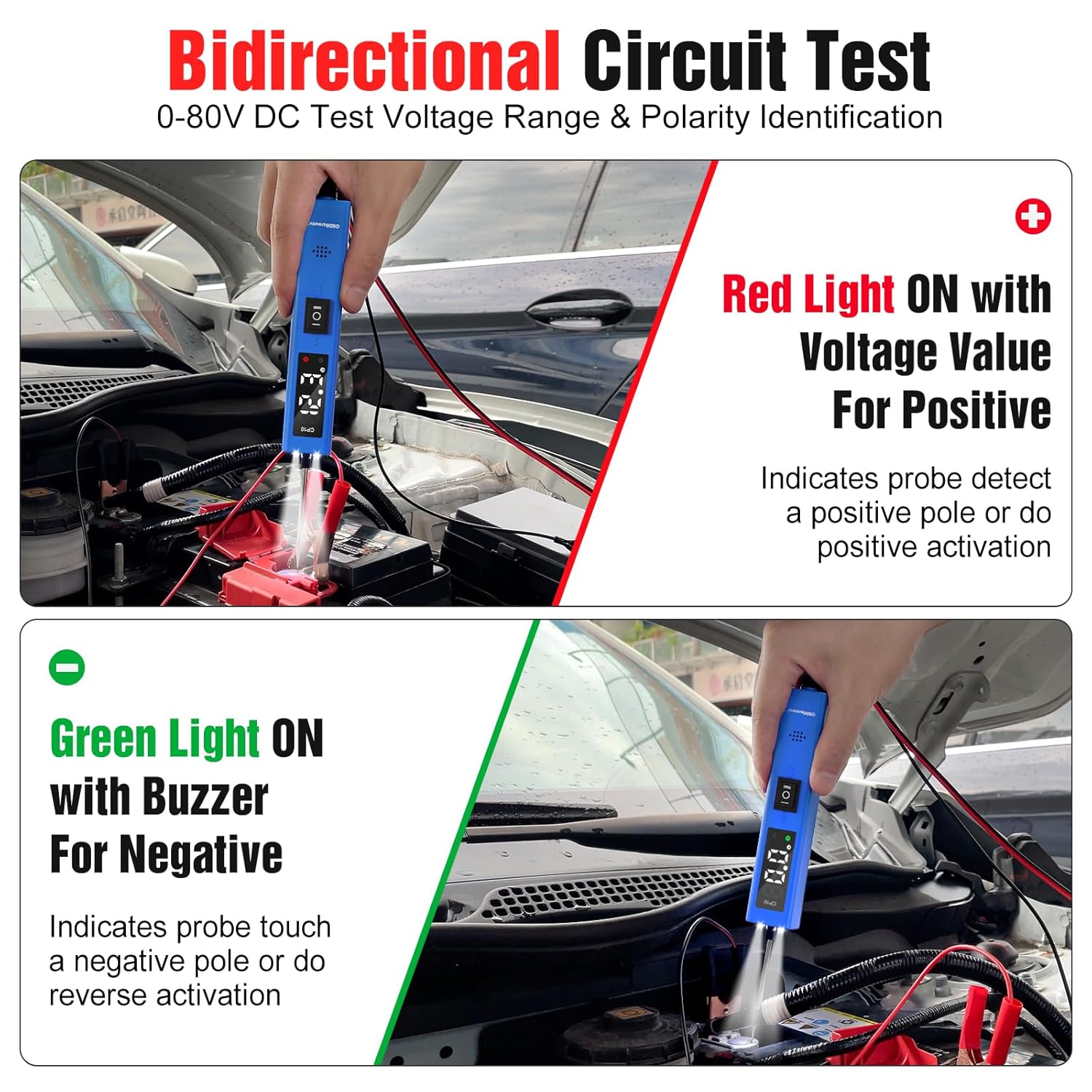
Obraz 5.1.1: Demonstrates bidirectional circuit testing. The top panel shows the red light illuminating with a voltage value for positive detection. The bottom panel shows the green light illuminating with a buzzer for negative detection.

Obraz 5.1.2: Illustrates the detection of positive, negative, and diode circuits. The LCD shows voltage readings for positive and diode tests, and 0.0 for negative tests, accompanied by corresponding LED indicators.
5.2 Aktywacja komponentów
This function allows you to activate components directly to test their functionality.
- Connect the tester to the vehicle battery.
- Touch the probe tip to the positive terminal of the component you wish to activate (e.g., starter, fuel pump, cooling fan).
- If the component requires a ground, ensure it is properly grounded or use the auxiliary ground clip.
- The tester will supply power to the component, allowing you to verify its operation.
- Be cautious not to activate components for extended periods to avoid overheating or damage.

Obraz 5.2.1: A diagram illustrating the setup for component activation, showing how the tester supplies power to a component to test its function.
5.3 Test ciągłości
To check for continuity in a wire or component:
- Upewnij się, że obwód lub element jest odłączony od zasilania.
- Connect the auxiliary ground clip to one end of the wire or component.
- Dotknij końcówką sondy drugiego końca.
- If continuity exists, the green LED will illuminate, and the buzzer will sound.
Obraz 5.3.1: A diagram illustrating the continuity test, showing the probe connected to a circuit and the green LED indicating continuity.
5.4 Short Circuit Location
The CP10 can help trace and locate short circuits:
- Isolate the circuit suspected of having a short.
- Connect the tester to the vehicle battery.
- Probe along the circuit path. The tester's voltage readings and polarity indicators can help pinpoint where the circuit deviates or grounds out unexpectedly.
5.5 Detekcja diody
Aby przetestować diody:
- Connect the tester to the vehicle battery.
- Touch the probe tip to one side of the diode and the auxiliary ground clip to the other.
- Obserwuj voltage reading on the LCD. A functional diode will show a voltage drop (e.g., 0.6V for silicon diodes) in one direction and an open circuit (no reading or very high resistance) in the reverse direction.
Obraz 5.5.1: Byłyample of diode detection, showing a voltage reading of 0.6V on the LCD display, indicating a functional diode.
5.6 Grounding Test
To test for a good ground connection:
- Connect the tester's main alligator clips to the vehicle battery.
- Touch the probe tip to the suspected ground point.
- If it's a good ground, the green LED will illuminate, and the LCD will display 0.0V.
Obraz 5.6.1: A diagram illustrating how to perform a ground detection test using the CP10.
5.7 Jump Lead Function
The CP10 can act as a temporary jump lead for certain applications:
- Connect the tester to the vehicle battery.
- Use the probe tip to supply power to a component that requires a temporary power source for testing.
- Always be mindful of the 8A overload protection. Do not attempt to power high-current devices that exceed this limit.
Obraz 5.7.1: A diagram illustrating the jumper function, showing how the tester can provide temporary power.
5.8 Wbudowana latarka
The CP10 features two built-in LED lights near the probe tip to illuminate dark work areas. These lights activate automatically when the device is powered on and connected to the vehicle battery.

Obraz 5.8.1: The CP10 tester with its two built-in LED lights actively illuminating a dark engine compartment, demonstrating its utility in low-light conditions.
6. Konserwacja
- Clean the probe tip and cables regularly with a dry, soft cloth.
- Store the tester in a dry, cool place, away from direct sunlight and corrosive materials.
- Inspect cables and clips for damage before each use. Replace if frayed or broken.
- The power switch is replaceable if it becomes damaged.
7. Rozwiązywanie Problemów
| Problem | Możliwa przyczyna | Rozwiązanie |
|---|---|---|
| Tester się nie włącza. | Incorrect battery connection; vehicle battery discharged; faulty power switch. | Ensure red clip is on positive (+), black on negative (-). Check vehicle battery voltage. Verify power switch is "ON". |
| Buzzer sounds and tester trips during operation. | Overload condition (current exceeds 8A); short circuit detected. | Disconnect the probe. Identify and resolve the overload or short circuit. Reconnect and test. |
| Niedokładna objtage odczyty. | Poor connection; dirty probe tip; faulty component. | Ensure firm contact with the circuit. Clean the probe tip. Test on a known good circuit to verify tester accuracy. |
| Latarka nie działa. | Tester not powered on; LED malfunction. | Ensure tester is connected to battery and powered on. If still not working, contact support. |
8. Specyfikacje
- Model: CP10
- Marka: Zasób OBD
- Objętość operacyjnatage: 12 V - 24 V prądu stałego
- TomtagZakres testu: 0-80V DC
- Zabezpieczenie przed przeciążeniem: 8A (Automatic trip with buzzer)
- Długość kabla: Około 16.5 stóp (5 metra)
- Waga przedmiotu: 236 gramów (8.32 uncji)
- Wymiary opakowania: 9.05 x 1.18 x 0.98 cala
- Kolor: Niebieski

Obraz 8.1.1: The OBDResource CP10 is compatible with a wide range of 12V and 24V vehicles, including cars, trucks, trailers, SUVs, motorcycles, boats, and riding mowers.
9. Gwarancja i wsparcie
For warranty information or technical support, please refer to the documentation included with your purchase or contact OBDResource customer service through their official channels. Keep your purchase receipt for warranty claims.