
1. Informacje dotyczące bezpieczeństwa
Read all safety warnings and instructions carefully before installing, operating, or performing maintenance on this heat pump system. Failure to follow these instructions may result in property damage, personal injury, or death.
- Wykwalifikowany personel: Installation and service must be performed by a qualified, licensed HVAC technician.
- Bezpieczeństwo elektryczne: Ensure the power supply is disconnected before performing any electrical work. Follow all local and national electrical codes.
- Postępowanie z czynnikiem chłodniczym: This system uses R-454B refrigerant. Only qualified personnel should handle refrigerants. Improper handling can cause injury or environmental damage.
- Ostre krawędzie: Be aware of sharp edges on metal parts during installation and maintenance. Wear appropriate personal protective equipment (PPE).
- Ciężki sprzęt: The outdoor and indoor units are heavy. Use proper lifting techniques and equipment to prevent injury.
2. Koniec produktuview
The ACiQ 1 Ton 21 SEER2 Central Inverter Heat Pump System is a high-efficiency heating and cooling solution designed for year-round comfort. It features advanced inverter technology for precise temperature control and reduced energy consumption.
Główne cechy:
- Technologia inwerterowa: Adjusts power based on demand, providing precise temperature control, reduced energy consumption, and quieter operation.
- Wysoka wydajność: 21 SEER2 rating for significant energy savings.
- Wydajność przez cały sezon: Capable of heating down to -13°F and cooling up to 122°F, ensuring comfort in extreme temperatures. Includes a chassis and crankcase heater for winter protection.
- Trwała konstrukcja: Features an aluminum coil for reliability and fiberglass-free insulation for improved efficiency and reduced condensation.
- Multi-Positional Air Handler: Supports horizontal, vertical, upflow, or downflow installation for versatile placement.
Komponenty systemu:
- Jednostka skraplacza zewnętrznego
- Jednostka przetwarzania powietrza wewnętrznego
- 5kW Back-up Heat Kit
- Smart LCD Thermostat

Figure 2.1: ACiQ Heat Pump System Components with Dimensions. The outdoor unit measures approximately 12.99 inches deep, 31.69 inches wide, and 21.81 inches high. The indoor air handler measures approximately 17.52 inches deep, 21.02 inches wide, and 45.00 inches high.
Wideo 2.2: Ponadview of ACiQ HPD/EHPD Condenser and System. This video provides a general introduction to the ACiQ heat pump condenser and overall system, highlighting its features and benefits.
3. Instalacja i konfiguracja
Proper installation is crucial for the optimal performance and longevity of your ACiQ heat pump system. This section provides general guidelines; always refer to the detailed installation manual provided with your unit for specific instructions.
3.1 Wybór miejsca
- Jednostka zewnętrzna: Select a location with adequate airflow, away from obstructions, and on a stable, level surface. Ensure sufficient clearance for maintenance.
- Indoor Air Handler: Choose a location that allows for efficient air distribution throughout the conditioned space. Consider accessibility for maintenance and filter changes.
3.2 Multi-Positional Air Handler Installation
The indoor air handler unit is designed for flexible installation to suit various home configurations. It can be installed in the following positions:
- Przepływ w górę: Air enters from the bottom and exits from the top.
- Przepływ w dół: Air enters from the top and exits from the bottom.
- Poziomo (lewo lub prawo): Air enters from one side and exits horizontally.

Figure 3.1: Multi-Positional Air Handler Unit. This diagram shows how the air handler can be configured for upflow, downflow, or horizontal airflow, providing versatility for different installation requirements.
3.3 Electrical and Refrigerant Connections
All electrical wiring and refrigerant line connections must be performed by a certified technician according to local codes and the detailed wiring diagrams provided in the full installation manual.
4. Instrukcja obsługi
Your ACiQ heat pump system is controlled by a smart LCD thermostat, offering intuitive control over your home's climate.
4.1 Funkcje termostatu
The smart LCD thermostat provides the following control options:
- Wybór trybu: Choose between Heating, Cooling, Fan Only, or Auto modes.
- Ustawienia temperatury: Adjust desired temperature setpoints.
- Ustawienia timera: Program the system to turn on or off at specific times.
- Harmonogram tygodniowy: Create custom heating and cooling schedules for different days of the week.
- Automatyczne ponowne uruchomienie: The system will automatically restart with previous settings after a power outage.
- Blokada dziecięca: Zapobiega nieautoryzowanym zmianom ustawień.
- Wyświetlanie kodu błędu: Provides diagnostic error codes for easier troubleshooting.

Figure 4.1: ACiQ Smart Thermostat and Wi-Fi Connected App. This image displays the user interface for controlling the ACiQ system via a smart thermostat and a mobile application, allowing for remote climate management.
4.2 Cooling and Heating Capacity
The inverter technology allows the system to maintain comfort across a wide range of outdoor temperatures.
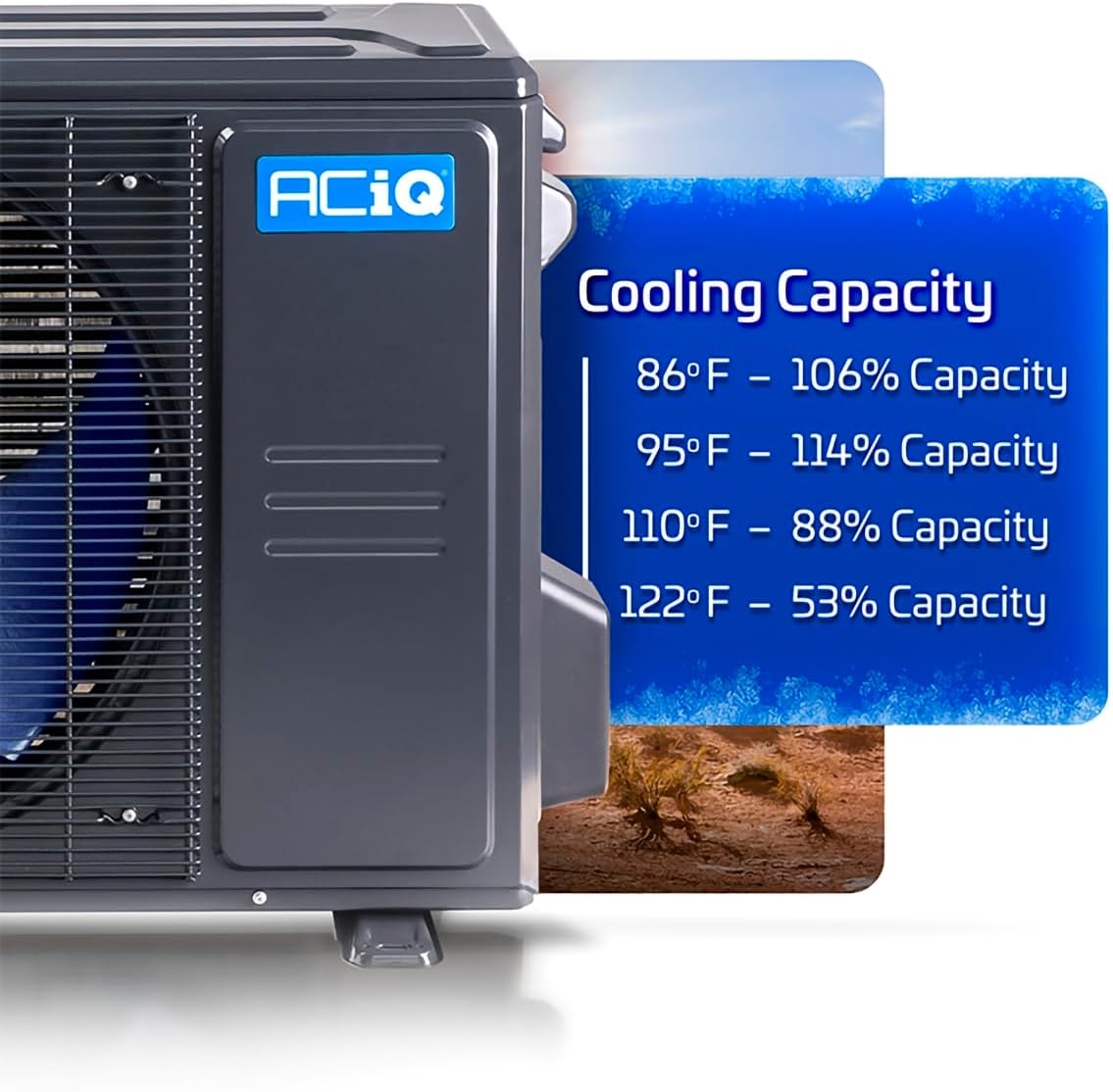
Figure 4.2: Cooling Capacity. This chart illustrates the system's cooling performance: 86°F - 106% Capacity, 95°F - 114% Capacity, 110°F - 88% Capacity, 122°F - 53% Capacity.

Figure 4.3: Heating Capacity. This chart illustrates the system's heating performance: -22°F - N/A, -13°F - 41% Capacity, 0°F - 56% Capacity, 17°F - 70% Capacity, 32°F - 84% Capacity.

Figure 4.4: Operation in Extreme Cold. The ACiQ heat pump is designed to operate effectively in cold conditions, providing heating down to -13°F.

Figure 4.5: Operation in Extreme Heat. The ACiQ heat pump maintains cooling performance even in high ambient temperatures, up to 122°F.
5. Konserwacja
Regular maintenance ensures the efficiency and longevity of your ACiQ heat pump system. Always disconnect power before performing any maintenance.
5.1 Wymiana filtra powietrza
Check and replace the air filter in the indoor air handler every 1-3 months, or more frequently if the system is used heavily or in dusty environments. A clean filter is essential for optimal airflow and indoor air quality.
5.2 Czyszczenie jednostki zewnętrznej
Keep the outdoor condenser unit free from debris such as leaves, grass clippings, and dirt. Periodically clean the coils with a soft brush or hose to ensure proper heat exchange. Do not use high-pressure washers.
5.3 Inspekcja profesjonalna
Zaleca się coroczne zlecenie inspekcji i serwisu systemu wykwalifikowanemu technikowi HVAC. Obejmuje to sprawdzenie poziomu czynnika chłodniczego, połączeń elektrycznych i ogólnej wydajności systemu.
6. Rozwiązywanie Problemów
This section provides basic troubleshooting steps for common issues. For complex problems or if these steps do not resolve the issue, contact a qualified HVAC technician.
| Problem | Możliwa przyczyna | Rozwiązanie |
|---|---|---|
| System nie grzeje/nie chłodzi | Incorrect thermostat setting, dirty air filter, power issue, low refrigerant | Check thermostat mode and temperature. Replace air filter. Check circuit breaker. Contact technician for refrigerant check. |
| Zmniejszony przepływ powietrza | Dirty air filter, blocked return/supply vents | Replace air filter. Clear any obstructions from vents. |
| Nietypowe dźwięki | Loose parts, fan obstruction, motor issue | Turn off system and inspect for loose panels or debris. If noise persists, contact technician. |
| Thermostat displays error code | Awaria systemu | Note the error code and consult the detailed thermostat manual or contact a technician. |
7. Specyfikacje
| Funkcja | Szczegół |
|---|---|
| Marka | ACiQ |
| Numer modelu | B0F3K8RDYN |
| Pojemność | 1 Ton (12000 British Thermal Units) |
| SEER2 Efficiency | 18.8 SEER2 |
| Typ czynnika chłodniczego | R-454B |
| Poziom hałasu | 33 decybeli |
| Wymiary jednostki zewnętrznej (gł. x szer. x wys.) | 13.46" x 35.04" x 26.5" |
| Typ instalacji | System dzielony |
| Cechy specjalne | Inverter Compressor, Smart Connectivity |
| Included Heat Kit | 5kW Back-up Heat Kit |
8. Gwarancja i wsparcie
8.1 warunków gwarancji
This ACiQ heat pump system comes with a comprehensive warranty:
- 7-letnia gwarancja na części
- 12-letnia gwarancja na kompresor
Note: Warranty terms are valid when the system is installed by a qualified technician and registered online with the manufacturer at no additional charge. Please refer to the official ACiQ warranty documentation for full details and registration procedures.
8.2 Obsługa klienta
For technical assistance, warranty claims, or further information, please contact ACiQ customer support. Contact details can typically be found on the manufacturer's webmiejscu lub w materiałach opakowaniowych.