
1. Koniec produktuview
The KUAIQU SPPS-K3010 is a high-precision variable DC power supply designed for laboratory, R&D, and industrial applications. It features a 5-digit TFT color display, offering both numerical and graphical (curve) representations of output voltage and current. This unit provides precise control over voltage (0-30V) and current (0-10A) with microampere-level resolution (0.01mA), ensuring accurate power delivery for sensitive electronic equipment.
Key features include advanced safety protections (Over-Voltage Protection - OVP, Over-Current Protection - OCP, Short-Circuit Protection - SCP), a memory function for storing and recalling up to four sets of parameters, and a user-friendly lock function to prevent accidental adjustments. It also incorporates USB-A and USB-C charging ports for convenience and an intelligent temperature-controlled cooling fan for stable, quiet operation.

Rycina 1.1: Przód view of the KUAIQU SPPS-K3010 DC Power Supply, showcasindzięki kompaktowej konstrukcji i wyraźnemu wyświetlaczowi.
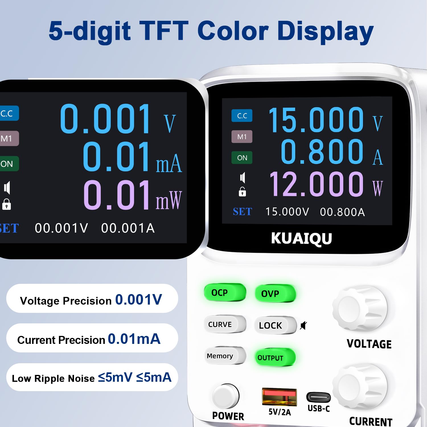
Figure 1.2: The 5-digit TFT color display provides high-precision readings, including 0.001V voltage precision and 0.01mA current precision.
2. Instrukcje bezpieczeństwa
Aby zapewnić bezpieczną obsługę i przedłużyć żywotność urządzenia, należy zapoznać się z poniższymi wytycznymi dotyczącymi bezpieczeństwa i stosować się do nich:
- Zawsze podłączaj zasilacz do uziemionego gniazdka elektrycznego.
- Nie używaj urządzenia w mokrym lub damp warunki.
- Zapewnij odpowiednią wentylację wokół urządzenia, aby zapobiec przegrzaniu. Nie blokuj otworów wentylacyjnych.
- Unikaj stosowania objętościtage or current exceeding the specified maximum ratings.
- Before making any connections or disconnections, ensure the output is turned off and the power supply is disconnected from the main power source.
- Nie otwierać casing zasilacza. Wewnątrz nie ma żadnych części, które mogłyby być naprawiane przez użytkownika. Wszelkie prace serwisowe należy zlecić wykwalifikowanemu personelowi.
- Trzymaj urządzenie z dala od materiałów łatwopalnych i gazów wybuchowych.
- Use only the provided power cable and output cables.
3. Składniki produktu
Familiarize yourself with the various components and controls of your KUAIQU SPPS-K3010 DC Power Supply.

Rysunek 3.1: Panel przedni z góryview. This image displays the front panel of the power supply, highlighting the TFT display, control buttons (OCP, OVP, CURVE, LOCK, Memory, OUTPUT), rotary encoder knobs for Voltage and Current, Power button, USB-A and USB-C charging ports, and output terminals (+, -, GND).
3.1 Elementy sterujące i wskaźniki na panelu przednim
- Kolorowy wyświetlacz TFT: Pokazuje tomtage, current, power, and curve displays.
- Przycisk OCP: Over-Current Protection setting and activation.
- Przycisk OVP: Over-voltage Protection setting and activation.
- Przycisk CURVE: Przełącza głośność w czasie rzeczywistymtage i wyświetlanie krzywej prądu.
- Przycisk blokujący: Locks/unlocks the control panel to prevent accidental changes.
- Przycisk pamięci: Uzyskuje dostęp i zapisuje wstępnie ustawioną głośnośćtage/current values (M1-M4).
- Przycisk WYJŚCIE: Włącza lub wyłącza moc wyjściową.
- TOMTAGGałka E: Rotary encoder for adjusting output voltage. Press to switch digit selection.
- Pokrętło CURRENT: Rotary encoder for adjusting output current. Press to switch digit selection.
- Przycisk zasilania: Główny wyłącznik zasilania urządzenia.
- USB-A / USB-C Ports: Do ładowania zewnętrznych urządzeń elektronicznych.
- Output Terminals (+, -, GND): Connect positive, negative, and ground leads to the load.
3.2 Panel tylny
The rear panel typically includes the AC power input socket, a fuse holder, and the cooling fan exhaust.
4. Konfiguracja
4.1 Rozpakowanie i kontrola
- Ostrożnie wyjmij zasilacz i wszystkie akcesoria z opakowania.
- Verify that all items listed in the "What's in the Box" section are present: 1x DC power supply, 1x output power cord, 1x power cord, 1x user manual.
- Inspect the unit for any signs of physical damage. If damage is found, contact your supplier immediately.
4.2 Połączenie zasilania
- Ensure the power supply's main power switch is in the OFF position.
- Connect the provided AC power cord to the power input socket on the rear panel of the power supply.
- Plug the other end of the AC power cord into a grounded electrical outlet (110V AC).
4.3 Podłączenie obciążenia
- Ensure the power supply's output is OFF (the OUTPUT button LED should be off).
- Connect the red output cable to the positive (+) terminal and the black output cable to the negative (-) terminal on the front panel.
- Connect the other ends of the output cables to your load device, ensuring correct polarity. For safety, connect the green ground (GND) terminal to the chassis of your load if required.
5. Instrukcja obsługi
5.1 Włączanie i wyłączanie zasilania
- Aby włączyć, naciśnij MOC przycisk. Wyświetlacz zostanie podświetlony.
- Aby wyłączyć, naciśnij MOC naciśnij przycisk ponownie.
5.2 Regulacja głośnościtage i Aktualne

Figure 5.1: Precision adjustment using encoder knobs. This image illustrates how to use the rotary encoder knobs for precise voltage and current adjustments, showing the process of pressing the knob to select digits and rotating to change values.
- Wybierz parametr: Obróć TOMTAGE or AKTUALNY knob to highlight the desired parameter on the display.
- Wybierz cyfrę: Naciśnij TOMTAGE or AKTUALNY knob to move the cursor to the digit you wish to adjust. Repeated presses cycle through the digits.
- Dostosuj wartość: Rotate the knob to increase or decrease the value of the selected digit.
- Potwierdzać: Once the desired value is set, stop rotating. The value will be applied.
5.3 Włączanie/wyłączanie wyjścia
Po ustawieniu żądanej głośnościtage i aktualne, naciśnij WYJŚCIE button to enable the power output to your load. The LED on the button will illuminate. Press it again to disable the output.
5.4 Memory Function (4 Groups of Storage)

Figure 5.2: Intelligent 4-group data storage. This image details the steps for using the memory function to store and recall up to four sets of voltage and current parameters (M1-M4).
- Wprowadź ustawienia: Naciśnij Pamięć przycisk.
- Select Memory Slot: Obróć TOMTAGE knob to select a memory slot (M1-M4).
- Set Values: Naciśnij i przytrzymaj TOMTAGE knob to enter setting mode. Short press and rotate the TOMTAGE/AKTUALNY knobs to set the desired voltage and current values for the selected slot.
- Zapisz ustawienia: Naciśnij i przytrzymaj TOMTAGE knob again to save the settings to the chosen memory slot.
- Ustawienia przywołania: To use a saved setting, rotate and short press the TOMTAGE knob to select the desired memory group (M1-M4) and then short press it again to apply.
5.5 Curve Display and Battery Simulation

Figure 5.3: Curve display and battery simulation. This image shows the real-time voltage and current curve display, useful for observing output stability and for applications like battery simulation and testing standby power consumption.
Naciśnij KRZYWA button to toggle the real-time voltage and current curve display. This feature allows for visual monitoring of output stability and transient behavior, which is particularly useful for tasks such as battery simulation and testing standby power consumption.
5.6 Intelligent A/mA Conversion
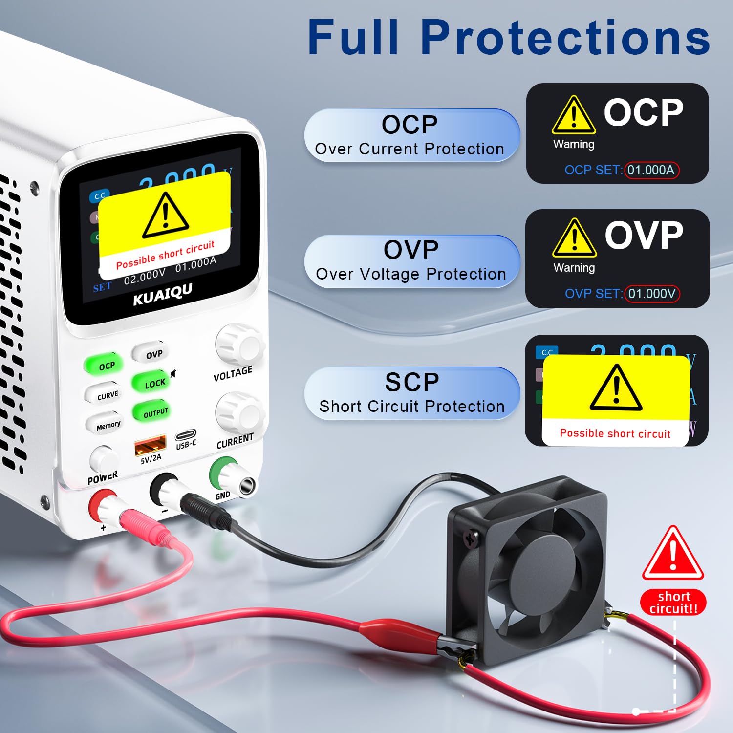
Figure 5.4: Intelligent A/mA Conversion. The display automatically switches to milliampere (mA) readings when the current value drops below 0.1A, providing enhanced precision for low-current applications.
The power supply automatically switches its current display from Amperes (A) to milliamperes (mA) when the output current drops below 0.1A. This intelligent conversion ensures optimal readability and precision for microampere-level measurements.
5.7 Protection Functions (OVP, OCP, SCP)
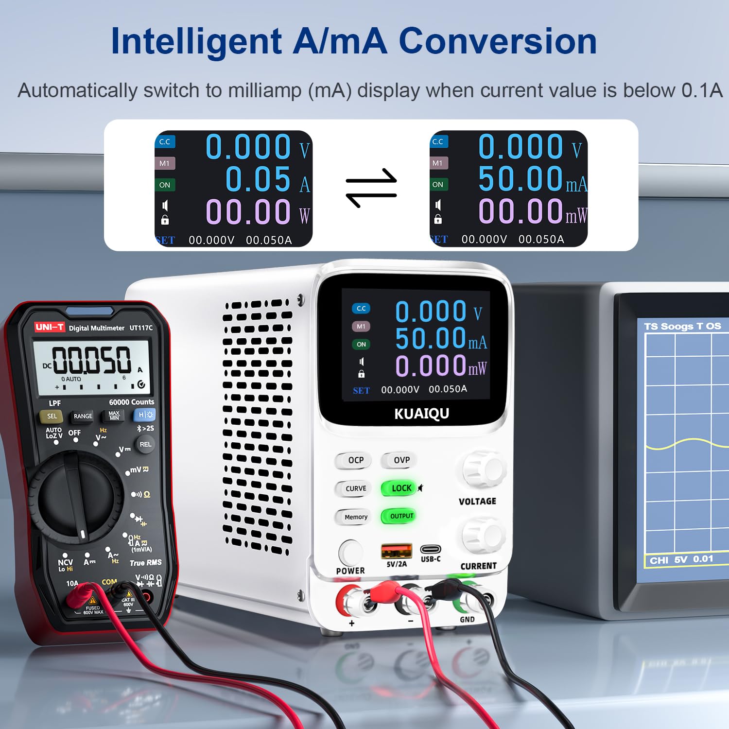
Figure 5.5: Full protection alarms. This image illustrates the Over-Current Protection (OCP), Over-Voltage Protection (OVP), and Short-Circuit Protection (SCP) features, showing how the device alerts and cuts off power when limits are exceeded or a short circuit is detected.
The power supply includes built-in protection mechanisms:
- Over-voltage Ochrona (OVP): Zapobiega objętości wyjściowejtage from exceeding a preset limit.
- Zabezpieczenie nadprądowe (OCP): Prevents output current from exceeding a preset limit.
- Short-Circuit Protection (SCP): Automatyczne odcięcie wyjścia w przypadku zwarcia.
To set OVP/OCP limits:
- Naciśnij i przytrzymaj OVP or OCP przycisk, aby wejść w tryb ustawień.
- Użyj TOMTAGE or AKTUALNY knob to adjust the protection limit.
- Naciśnij krótko OVP or OCP ponownie, aby zapisać ustawienie.
If a protection is triggered, the output will be cut off, and an alarm will be displayed (e.g., "OVP", "OCP", or "Possible short circuit"). Address the issue and then press the WYJŚCIE przycisk, aby ponownie włączyć wyjście.
5.8 Funkcja blokady
Naciśnij ZAMEK button to lock the control panel, preventing accidental changes to settings. The lock icon will appear on the display. Press it again to unlock. Long pressing the ZAMEK button will toggle the encoder knob adjustment beeping sound.
5.9 porty ładowania USB
The front panel includes USB-A and USB-C ports (5V/2A) for convenient charging of compatible electronic devices. These ports operate independently of the main power output settings.
6. Konserwacja
6.1 Czyszczenie
- Before cleaning, ensure the power supply is turned off and disconnected from the main power source.
- Do przecierania zewnętrznej części urządzenia należy używać miękkiej, suchej ściereczki.
- Nie należy używać środków czyszczących o działaniu ściernym, rozpuszczalników ani silnych środków chemicznych.
- Periodically check the ventilation openings for dust accumulation and clean gently with a soft brush or compressed air.
6.2 Przechowywanie
- Store the power supply in a cool, dry environment, away from direct sunlight and extreme temperatures.
- Przechowywać z dala od kurzu i wilgoci.
- If storing for an extended period, it is recommended to place it back in its original packaging.
7. Rozwiązywanie Problemów
W tej sekcji omówiono typowe problemy, które mogą wystąpić. Jeśli problem będzie się powtarzał, skontaktuj się z obsługą klienta.
7.1 No Power / Display Off
- Sprawdź kabel zasilający: Upewnij się, że kabel zasilania prądem zmiennym jest prawidłowo podłączony do zasilacza i gniazdka ściennego.
- Sprawdź gniazdko ścienne: Sprawdź, czy gniazdko ścienne działa prawidłowo, podłączając do niego inne urządzenie.
- Sprawdź wyłącznik zasilania: Ensure the main MOC button on the front panel is pressed.
- Sprawdź bezpiecznik: The fuse located on the rear panel might be blown. Replace it with a fuse of the same type and rating (refer to specifications).
7.2 Brak objętości wyjściowejtage/Bieżący
- Check OUTPUT Button: Zapewnij WYJŚCIE button is pressed and its LED is illuminated.
- Sprawdź połączenia: Verify that the output cables are correctly and securely connected to both the power supply and the load.
- Check OVP/OCP: If OVP or OCP is triggered, the output will be disabled. Check the display for "OVP" or "OCP" warnings. Adjust the voltage/current settings or protection limits as needed, then press WYJŚCIE to re-enable.
- Check Short Circuit: If "Possible short circuit" is displayed, disconnect the load and check for any short circuits in your circuit.
- Tomtage/Ustawienia bieżące: Upewnij się, że ustawiona objętośćtage and current values are not zero.
7.3 Problemy z wyświetlaniem
- Brak wyświetlacza: Refer to "No Power / Display Off" section.
- Nieprawidłowe odczyty: Ensure proper connections and calibration. If readings are consistently inaccurate, contact support.
8. Specyfikacje
| Funkcja | Specyfikacja |
|---|---|
| Nazwa modelu | SPPS-K3010 |
| Marka | KUAIQU |
| Objętość wyjściatage Zakres | 0-30 V |
| Zakres prądu wyjściowego | 0-10A |
| Moc wyjściowatage | 300 watów |
| Tomtage Rozdzielczość | 0.001V (1mV) |
| Aktualna rozdzielczość | 0.01mA (10µA) |
| Wyświetlacz | 2.8-inch TFT Color LCD (5-digit) |
| Funkcje ochronne | OVP (Over-Voltage Protection), OCP (Over-Current Protection), SCP (Short-Circuit Protection) |
| Pamięć masowa | 4 groups of editable parameters |
| Porty ładowania USB | USB-A, USB-C (5V/2A) |
| Metoda chłodzenia | Intelligent temperature-controlled cooling fan |
| Wymiary produktu (dł. x szer. x wys.) | 7.6 x 3.4 x 5.5 cala |
| Waga przedmiotu | 2.5 funtów |
| UPC | 768351108799 |
9. Gwarancja i obsługa klienta
KUAIQU is committed to providing high-quality products and excellent customer service. This product undergoes thorough inspection before shipment to ensure its quality.
- Zapewnienie jakości: All KUAIQU lab power supplies and accessories are inspected to ensure good quality upon receipt.
- Wsparcie techniczne: If you have any questions regarding the operation, troubleshooting, or any other aspect of your KUAIQU SPPS-K3010 DC Power Supply, please do not hesitate to contact our customer service team.
- Informacje kontaktowe: Refer to the contact details provided with your purchase or visit the official KUAIQU webwitryna wsparcia.