1. Wprowadzenie
This manual provides essential instructions for the installation, operation, and maintenance of your PowMr 5000W Off-Grid Hybrid Solar Inverter. Please read this manual thoroughly before installation and operation to ensure proper use and to prevent damage to the unit or injury to personnel. Keep this manual for future reference.
2. Instrukcje bezpieczeństwa
WARNING: This section contains important safety instructions that must be followed during installation and operation of the inverter. Failure to follow these instructions may result in severe injury or death.
- Upewnij się, że całe okablowanie zostało wykonane przez wykwalifikowany personel.
- Nie należy podejmować prób demontażu ani naprawy falownika. Wewnątrz nie ma żadnych części, które mogłyby zostać naprawione przez użytkownika.
- Disconnect all power sources (PV array, battery, AC input) before performing any wiring or maintenance.
- Należy nosić odpowiedni sprzęt ochrony osobistej (PPE), w tym rękawice termoizolacyjne i okulary ochronne.
- Falownik należy zamontować w dobrze wentylowanym pomieszczeniu, z dala od materiałów łatwopalnych i gazów żrących.
- Zapewnij prawidłowe uziemienie falownika.
- The battery bank must be properly sized and protected with appropriate circuit breakers or fuses.
3. Koniec produktuview
3.1 Funkcje
- 5000W low-frequency pure sine wave inverter with 15000W peak power.
- Wbudowany regulator ładowania słonecznego MPPT 120A.
- Compatible with 48V AGM, Gel, Lead-acid, Lithium-ion, and LiFePO4 batteries.
- Supports 4 charging modes: Only Solar, Mains Priority, Solar Priority, and Hybrid (Mains & Solar).
- Offers 2 output modes: Mains bypass and Inverter output.
- LCD display and 3 LED indicators for real-time monitoring and fault code display.
- Toroidal transformer design for stable and reliable operation.
- Intelligent variable-speed fan for efficient heat dissipation.
- Comprehensive battery protection features including short circuit, over/under voltage protection, and lithium activation.
3.2 Identyfikacja komponentów
The PowMr 5000W Solar Inverter features a robust design with clearly labeled connection points and an intuitive display panel.
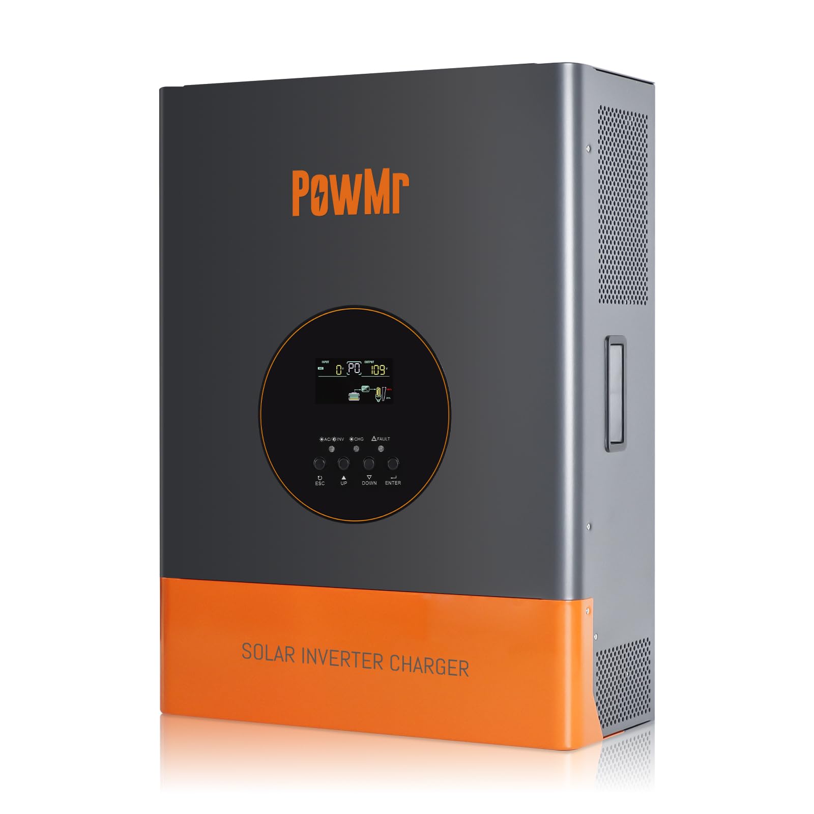
Obraz 1: Przód view of the PowMr 5000W Solar Inverter. This image displays the main unit, highlighting its compact form factor and the location of the LCD display and control buttons on the front panel. The cooling fins are visible on the sides, indicating its heat dissipation design.
- Panel przedni: LCD display, LED indicators (Power, Fault, Charge), function buttons.
- Tylny panel: AC input/output terminals, PV input terminals, Battery terminals, Communication ports, Cooling fan.
4. Konfiguracja
4.1 Wybór miejsca
- Mount the inverter indoors, away from direct sunlight, rain, and moisture.
- Ensure ambient temperature is between 0°C and 55°C (32°F and 131°F).
- Aby zapewnić właściwy przepływ powietrza, należy zachować odstęp co najmniej 20 cm (8 cali) wokół falownika.
- The mounting surface must be strong enough to support the inverter's weight (approximately 59.4 lbs).
4.2 Montaż falownika
- Zaznacz pozycje śrub montażowych na ścianie.
- W razie potrzeby wywierć otwory i włóż kotwy ścienne.
- Securely mount the inverter to the wall using appropriate screws.
4.3 połączeń przewodów
IMPORTANT: All wiring must comply with local and national electrical codes. Ensure all connections are tight and secure.
- Podłączenie akumulatora: Connect the 48V battery bank to the inverter's battery terminals. Ensure correct polarity (positive to positive, negative to negative). Use appropriate cable gauges and fuses/breakers.
- Podłączenie układu fotowoltaicznego: Connect the solar panel array to the PV input terminals. Verify that the PV array's open circuit voltage (Voc) does not exceed 150Vdc and the MPPT voltage range is 60~150Vdc. Ensure correct polarity.
- Podłączenie wejścia AC: Connect the utility grid or generator AC power to the AC input terminals. Install an external circuit breaker for protection.
- Podłączenie wyjściowe prądu przemiennego: Connect your AC loads to the AC output terminals. Install an external circuit breaker for protection.
- Grunt: Podłącz zacisk uziemienia falownika do niezawodnego uziemienia.
5. Obsługa
5.1 Pierwsze uruchomienie
- Po wykonaniu i sprawdzeniu wszystkich połączeń włącz wyłącznik akumulatora.
- Włącz wyłącznik układu fotowoltaicznego.
- Switch on the AC input breaker (if connected).
- Press and hold the power button on the inverter for a few seconds to turn it on.
- The LCD display will illuminate, and the inverter will begin its self-test sequence.
5.2 Wyświetlacz LCD i wskaźniki
The LCD display provides real-time system data such as input/output voltage, current, frequency, battery status, and operating mode. The three LED indicators show:
- Dioda LED zasilania: Indicates inverter power status.
- Dioda błędu: Illuminates when a fault occurs, displaying a corresponding fault code on the LCD.
- Dioda ładowania: Wskazuje stan naładowania akumulatora.
Use the function buttons to navigate through the display menus and configure settings such as charging modes and output modes.
5.3 tryby pracy
The inverter supports various operating modes to optimize power usage:
- Tryby ładowania: Only Solar, Mains Priority, Solar Priority, Hybrid (Mains & Solar). Select the mode that best suits your energy needs and grid availability.
- Tryby wyjściowe: Mains bypass (loads powered directly by grid/generator) and Inverter output (loads powered by inverter from battery/PV).
5.4 Procedura wyłączania
- Turn off all AC loads connected to the inverter.
- Press and hold the power button on the inverter to turn it off.
- Switch off the AC input breaker.
- Switch off the PV array breaker.
- Switch off the battery breaker.
6. Konserwacja
6.1 Regularne kontrole
- Okresowo należy sprawdzać wszystkie połączenia przewodów pod kątem szczelności i oznak korozji.
- Check the inverter's ventilation openings for dust or obstructions.
- Monitoruj wyświetlacz LCD pod kątem ostrzeżeń lub komunikatów o błędach.
6.2 Czyszczenie
- Ensure the inverter is powered off and all power sources are disconnected before cleaning.
- Use a soft, dry cloth to wipe the exterior of the inverter.
- Nie należy używać płynnych środków czyszczących ani rozpuszczalników.
- Clean the cooling fan vents to ensure proper heat dissipation.
6.3 Konserwacja akumulatora
Refer to your battery manufacturer's guidelines for specific maintenance procedures. Ensure battery terminals are clean and free of corrosion. For lead-acid batteries, check electrolyte levels periodically if applicable.
7. Rozwiązywanie Problemów
If the inverter is not operating correctly, refer to the following common issues and solutions. For persistent problems, contact technical support.
| Problem | Możliwa przyczyna | Rozwiązanie |
|---|---|---|
| Falownik się nie włącza | Brak połączenia z baterią lub niski poziom naładowania bateriitage | Sprawdź połączenia akumulatora i objtage. Charge battery if low. |
| Brak wyjścia AC | Przeciążenie, zwarcie lub stan usterki | Reduce load, check for short circuits, refer to LCD fault code. |
| Bateria się nie ładuje | PV array disconnected, low PV voltage, or charger fault | Check PV connections, ensure sufficient sunlight, verify PV voltage. |
| Zapalona dioda LED sygnalizująca usterkę | Internal fault or protection triggered | Note the fault code on the LCD display and consult the specific fault code section in the full manual (if available) or contact support. |
8. Specyfikacje
| Parametr | Wartość |
|---|---|
| Znamionowa moc wyjściowa | 5000 W |
| Moc szczytowa | 15000 W |
| Znamionowa moc wyjściowatage Zakres | 110Vac ± 10% |
| Znamionowe napięcie wejściowe DCtage | 48 V prądu stałego |
| Maks. Moc panelu PV | 6400 W |
| Obj. wejścia MPPTtage Zakres | 60~150 V prądu stałego |
| Maks. Objętość otwartego obwodu tablicy fotowoltaicznejtage | 150 V prądu stałego |
| Maksymalny prąd ładowania AC | 29A |
| Maks. Prąd ładowania PV | 120A |
| Efektywność | >98% |
| Wymiary produktu (dł. x szer. x wys.) | 15 x 7 x 20 cala |
| Waga przedmiotu | 59.4 funta |
| Numer modelu | POW-RELAB-5KU |
| Producent | Pan Pow |
9. Gwarancja i wsparcie
This PowMr inverter comes with a manufacturer's warranty. Please refer to the warranty card included with your product for detailed terms and conditions, including warranty period and coverage.
For technical support, troubleshooting assistance, or warranty claims, please contact PowMr customer service through the retailer where the product was purchased or visit the official PowMr webwitryna do informacji kontaktowych.