
1. Wprowadzenie
This manual provides essential information for the safe and efficient operation of your TYAN MiTAC Thunder CX GC68A-B7126 B7126G68AV10E2HR -1U2S Cloud Server. It covers installation, configuration, maintenance, and troubleshooting procedures. Please read this manual thoroughly before installing or operating the server.
2. Informacje dotyczące bezpieczeństwa
Aby zapobiec obrażeniom ciała i uszkodzeniom sprzętu, należy przestrzegać następujących środków ostrożności:
- Przed przystąpieniem do prac konserwacyjnych lub instalacyjnych należy zawsze odłączyć zasilanie.
- Zapewnij odpowiednie uziemienie, aby zapobiec porażeniu prądem.
- Handle components with care to avoid electrostatic discharge (ESD) damage. Use an anti-static wrist strap.
- Do not operate the server in environments with excessive heat, humidity, or dust.
- Ensure adequate ventilation around the server to prevent overheating.
3. Zawartość opakowania
Verify that all items are present and undamaged. If any items are missing or damaged, contact your vendor immediately.
- TYAN MiTAC Thunder CX GC68A-B7126 Server Unit
- Power Cords (quantity may vary by region)
- Rackmount Rail Kit
- Documentation (Quick Start Guide, CD/USB with drivers and utilities)
- Accessory Kit (screws, cables, etc.)
4. Przekroczenie fizyczneview
W tej sekcji znajdziesz więcejview of the server's external and internal components.
4.1 Przód i Tył View
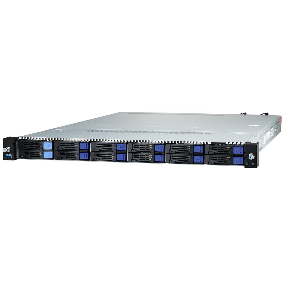
Figure 4.1: Combined front and rear view of the server, showing hot-swap drive bays on the front and I/O ports and redundant power supplies on the rear.
4.2 Panel przedni
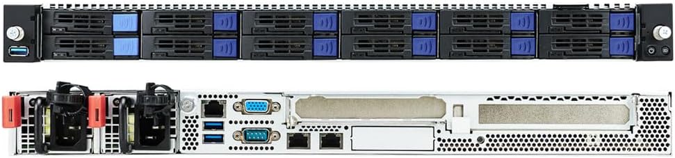
Figure 4.2: Close-up of the server's front panel, featuring 12 hot-swap 2.5-inch drive bays, USB ports, and system status LEDs.
4.3 Internal Layout
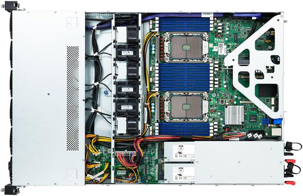
Rysunek 4.3: Wewnętrzne view of the server, showcasing the motherboard with DIMM slots, CPU sockets, PCIe slots, and cooling fan modules.
5. Konfiguracja
5.1 Instalacja w stojaku
The server is designed for installation in a standard 19-inch rack. Follow the instructions provided with the rackmount rail kit to securely mount the server.
5.2 Instalacja komponentów
Before installing components, ensure the server is powered off and disconnected from the power source.
5.2.1 Memory (DIMMs) Installation
- Open the server chassis cover.
- Znajdź gniazda DIMM na płycie głównej.
- Open the retaining clips at both ends of the DIMM slot.
- Align the memory module with the slot key and press firmly until the clips snap into place.
- Ensure all DIMMs are seated correctly.
5.2.2 Instalacja dysku pamięci masowej
The server supports 2.5-inch hot-swap SATA and NVMe drives.
- For hot-swap drives, ensure the drive tray is empty.
- Mount the 2.5-inch drive into the drive tray using the provided screws.
- Slide the drive tray into an available hot-swap bay until it clicks into place.
- For M.2 NVMe drives, open the chassis and locate the M.2 slot on the motherboard. Install the M.2 drive and secure it with the screw.
5.2.3 Instalacja karty PCIe
The server features 2 x FH/HL PCIe Gen4 x16 slots.
- Open the server chassis cover.
- Remove the blanking plate from the desired PCIe slot.
- Carefully insert the PCIe card into the slot, ensuring it is fully seated.
- Secure the card with the retaining mechanism or screw.
5.3 Okablowanie
- Kable zasilające: Connect the redundant power supplies to separate power sources for redundancy.
- Kable sieciowe: Connect the GbE ports to your network infrastructure. Connect the dedicated IPMI port for remote management.
- Peripheral Cables: Connect any necessary USB devices, keyboard, mouse, or VGA monitor.
5.4 Pierwsze włączenie zasilania
After all components are installed and cables connected, press the power button on the front panel. Observe the system LEDs for normal operation. The server should initiate the boot process.
6. Obsługa serwera
6.1 Konfiguracja BIOS/UEFI
Aby uzyskać dostęp do narzędzia konfiguracji BIOS/UEFI, naciśnij wyznaczony klawisz (zwykle USUNĄĆ or F2) during the Power-On Self-Test (POST) sequence. Here you can configure boot order, system time, and other hardware settings.
6.2 Instalacja systemu operacyjnego
Insert your operating system installation media (USB drive or network boot) and configure the boot order in BIOS/UEFI to start from the installation media. Follow the on-screen instructions to install your preferred operating system.
6.3 IPMI Management
The Intelligent Platform Management Interface (IPMI) allows for remote monitoring and management of the server, even when the main operating system is not running. Connect the dedicated IPMI LAN port to your network. Access the IPMI web interfejs przez a web browser using the assigned IP address. Refer to the IPMI user guide for detailed instructions.
7. Konserwacja
Regular maintenance ensures optimal performance and longevity of your server.
7.1 aktualizacji oprogramowania sprzętowego
Okresowo sprawdzaj producenta website for updated BIOS, BMC, and other component firmware. Keeping firmware up-to-date can improve stability, performance, and security. Follow the provided instructions carefully during the update process.
7.2 Wymiana podzespołów
- Hot-Swap Drives: Drives can be replaced without powering down the server. Ensure the replacement drive is compatible and follow the operating system's procedures for drive replacement in a RAID configuration.
- Redundant Power Supplies: The server features hot-swappable redundant power supplies. If one PSU fails, it can be replaced while the server remains operational. Disconnect the failed PSU, remove it, and insert the new one.
7.3 Czyszczenie
Dust accumulation can impede airflow and cause overheating. Periodically clean the server's interior using compressed air. Ensure the server is powered off and disconnected from power before cleaning. Do not use liquid cleaners directly on components.
8. Rozwiązywanie Problemów
W tej sekcji znajdziesz rozwiązania typowych problemów, na jakie możesz natrafić.
8.1 Typowe problemy i rozwiązania
- Brak zasilania: Check power cable connections, power supply status LEDs, and ensure power outlets are functional.
- Błąd rozruchu: Verify boot order in BIOS/UEFI, check for loose memory modules or expansion cards, and ensure storage drives are detected.
- Problemy z łącznością sieciową: Check network cable connections, network adapter status LEDs, and network configuration in the operating system.
- Przegrzanie: Ensure proper ventilation, clean dust from fans and heatsinks, and check ambient temperature.
8.2 Wskaźniki LED
Refer to the server's front panel and internal LEDs for diagnostic information. Different LED patterns or colors indicate specific system statuses or errors. Consult the detailed hardware manual for a complete list of LED codes.
9. Specyfikacje
| Funkcja | Specyfikacja |
|---|---|
| Marka | Tyan |
| Nazwa modelu | B7126G68AV10E2HR |
| Edytor | Intel (others) |
| Technologia RAM | DDR4 |
| Rozmiar zainstalowanej pamięci RAM | 1 TB |
| RAM Maximum Size | 1 TB |
| Typ dysku twardego | Dysk SSD |
| Interfejs dysku twardego | eSATA |
| Prędkość obrotowa dysku twardego | 7200 obr./min. |
| Karta graficzna | Zintegrowany |
| Porty USB 2.0 | 1 |
| Porty USB 3.0 | 1 |
| Waga przedmiotu | 49 funta |
| Wymiary opakowania | 38 x 23 x 10 cala |
| Konkretne zastosowania | Biznes |
10. Gwarancja i wsparcie
This TYAN server comes with a standard manufacturer's warranty. For detailed warranty terms and conditions, please refer to the warranty card included with your product or visit the official Tyan website. For technical support, driver downloads, and further assistance, please contact Tyan customer service or your authorized reseller.