1. Wprowadzenie
This manual provides detailed instructions for the Acouto 5V-24V Motor Control Board, a versatile module designed for controlling DC/AC motor forward and reverse operations with integrated time delay relay functions. It supports multiple control modes and offers customizable timing and cycle settings for various applications.
2. Koniec produktuview

Rycina 1: Przód view of the Acouto motor control board, featuring a digital display, two blue relays, and several control buttons (SET, ++, --, OK) on the right side. Input and output terminals are visible along the edges.
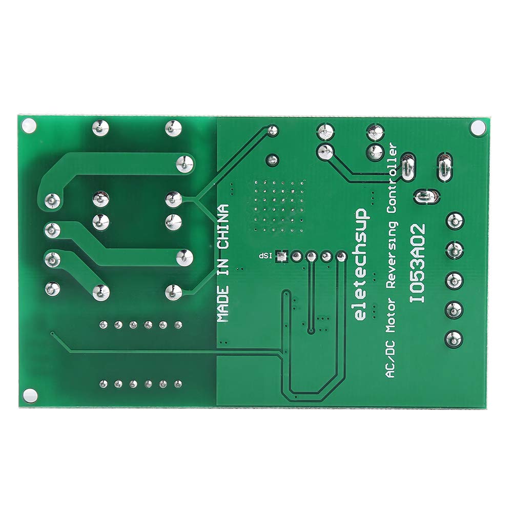
Rysunek 2: Tył view of the Acouto motor control board, displaying the green PCB with circuit traces and the text 'MADE IN CHINA' and 'eletechsup AC/DC Motor Reversing Controller 1053A02'.
2.1 Główne cechy
- Wszechstronne opcje sterowania: Offers input control options for forward, reverse, and stop functions, catering to various user preferences and needs.
- Flexible Trigger Modes: Supports two input trigger modes: Low-Pulse trigger mode and Low-Level trigger mode, allowing users to select the mode that suits their application for accurate and efficient motor control.
- Możliwość dostosowania czasu opóźnienia: Features a precise timing control with delay options ranging from 0.1 seconds to 9999 minutes, enabling users to tailor the controller's performance to specific requirements.
- Effective Cycle Options: Cycle times can be set to no cycle, 2-99 cycles, or always cycle, providing flexibility to customize motor operation and achieve optimal results in various scenarios.
- Clear Indicator Lights: Equipped with three LED indicators (Forward, Reverse, Stop) for easy monitoring of the motor's status at a glance, ensuring quick and efficient troubleshooting when necessary.
3. Specyfikacje
- Zasilanie: Two options (do not power simultaneously):
- Power Supply 1 (DC 5.5MM female jack): DC 5V
- Power Supply 2 (VIN/GND terminals): DC 6.5-25V
- Prąd roboczy:
- Normal Mode: Standby 41mA, Working 83mA
- Energy-Saving Mode: Standby 7mA, Working 44mA
- Input Control Ports: Forward (FWD), Reverse (REV), Stop (STOP)
- Input Trigger Modes: Low-Pulse trigger mode, Low-Level trigger mode
- Zakres czasu opóźnienia: 0.1-999.9 seconds, 1-9999 seconds, 1-9999 minutes
- Czasy cyklu: No cycle, 2-99 cycles, Always cycle
- Wskaźniki: Forward (F LED), Reverse (R LED), Stop (S LED)
- Relay Load Current: Recommended less than 5A
3.1 Opisy portów
- DC 5.5MM female: Power supply 1, DC 5V input.
- VIN: Power supply 2 positive, DC 6.5-25V input.
- masa: Power supply 2 negative.
- Przód: Forward input control (functionality may vary based on selected mode).
- OBRÓT SILNIKA: Reverse input control (functionality may vary based on selected mode).
- ZATRZYMYWAĆ SIĘ: Stop input control (functionality may vary based on selected mode).
- M+: Motor positive output.
- M-: Motor negative output.
- P+: Positive terminal for motor power supply (if separate motor power is used).

Figure 3: Dimensions of the control board, measuring approximately 8cm (3.2in) in length and 3.2cm (2in) in width.
4. Konfiguracja i instalacja
4.1 Połączenie zasilania
- Choose one power supply option: either connect a DC 5V power source to the DC 5.5MM female jack, or connect a DC 6.5-25V power source to the VIN and GND terminals. Do not connect both power supplies simultaneously.
- Upewnij się, że napięcie zasilaniatage is within the specified range to prevent damage to the module.
4.2 Podłączenie silnika
- Connect the positive terminal of your DC motor to the M+ terminal on the control board.
- Connect the negative terminal of your DC motor to the M- terminal on the control board.
- If your motor requires a separate power supply, connect its positive terminal to P+ and its negative terminal to M-. Ensure the motor power supply is appropriate for your motor.
- Ensure the relay load current does not exceed the recommended 5A.
4.3 Control Input Connections

Rysunek 4: Kątowy view highlighting the VIN, GND, FWD, REV, and STOP input terminals for power and control signals.
- Connect your control signals (e.g., from buttons, microcontrollers) to the FWD, REV, and STOP input terminals.
- Refer to the specific function mode selected for how these inputs will trigger actions (Low-Pulse or Low-Level).
5. Instrukcja obsługi
The control board features a digital display and several buttons (SET, ++, --, OK) for configuration. The exact operational modes and their settings are determined by the firmware. This section provides general guidance.

Figure 5: Close-up of the control buttons and digital display, used for setting parameters.
5.1 Podstawowa obsługa
- Forward Control: Apply a trigger signal to the FWD input. The F LED will illuminate, and the motor will run in the forward direction.
- Reverse Control: Apply a trigger signal to the REV input. The R LED will illuminate, and the motor will run in the reverse direction.
- Stop Control: Apply a trigger signal to the STOP input. The S LED will illuminate, and the motor will stop.
5.2 Setting Delay Times and Cycles
- Naciśnij USTAWIĆ button to enter the parameter setting mode. The digital display will show the current parameter.
- Użyj ++ I -- buttons to adjust the value of the displayed parameter (e.g., delay time, cycle count).
- Naciskać USTAWIĆ again to move to the next parameter or to confirm the current setting.
- Naciśnij OK button to save all settings and exit the parameter setting mode.
- The delay time can be set in seconds (0.1-999.9s, 1-9999s) or minutes (1-9999min). The unit is typically indicated on the display or by a specific mode.
- Cycle times can be configured for no cycle, a specific number of cycles (2-99), or continuous cycling.
6. Konserwacja
- Keep the control board clean and free from dust and moisture.
- Unikaj wystawiania płytki na działanie ekstremalnych temperatur i bezpośredniego światła słonecznego.
- Regularly check all wire connections to ensure they are secure.
- Do not attempt to repair the board if you are not qualified. Contact a professional if issues arise.
7. Rozwiązywanie Problemów
- Brak zasilania/wyłączony wyświetlacz:
- Check power supply connections and ensure voltage is within the specified range (DC 5V or DC 6.5-25V).
- Verify that only one power supply option is connected.
- Silnik nie reaguje:
- Ensure motor connections (M+, M-) are correct and secure.
- Check if the control input signals (FWD, REV, STOP) are being correctly applied according to the selected trigger mode.
- Verify that the motor's current draw does not exceed the relay's 5A capacity.
- Confirm that the selected operating mode and delay settings are appropriate.
- Nieprawidłowy kierunek obrotów silnika:
- Reverse the M+ and M- connections to change the motor's default direction.
- Wskaźniki LED nie działają:
- Ensure the board is powered correctly and the corresponding function is active.
8. Informacje dotyczące bezpieczeństwa
- Always disconnect power before making any connections or adjustments to the board.
- Ensure proper insulation for all wiring to prevent short circuits.
- Nie przekraczaj określonej objętościtage and current ratings for the power supply and motor load.
- This product is an electronic component; handle with care to avoid electrostatic discharge.
- Przechowywać w miejscu niedostępnym dla dzieci.