
1. Wprowadzenie
This manual provides detailed instructions for the installation, configuration, and operation of your SODOLA 6-Port 10G Web Managed Ethernet Switch. This high-performance switch is designed to enhance network connectivity with its 4x10G RJ45 ports and 2x10G SFP+ ports, supporting various speeds and advanced management features.

Figure 1: SODOLA 6-Port 10G Web Managed Ethernet Switch (Model: 4x10G RJ45+2x10G SFP+)
The switch is compliant with IEEE 802.3, IEEE 802.3u, IEEE 802.3ab, IEEE 802.3bz, and IEEE 802.3ae standards, ensuring broad compatibility and reliable performance for demanding network environments.
2. Zawartość opakowania
Verify that all items are present and in good condition. If any item is missing or damaged, please contact your vendor.
- 1 x SODOLA 6-Port 10G Managed Ethernet Switch
- 1 x Instrukcja obsługi
- 1 x Przewód zasilający
- 4 x podnóżki
- 1 x Certificate of Inspection
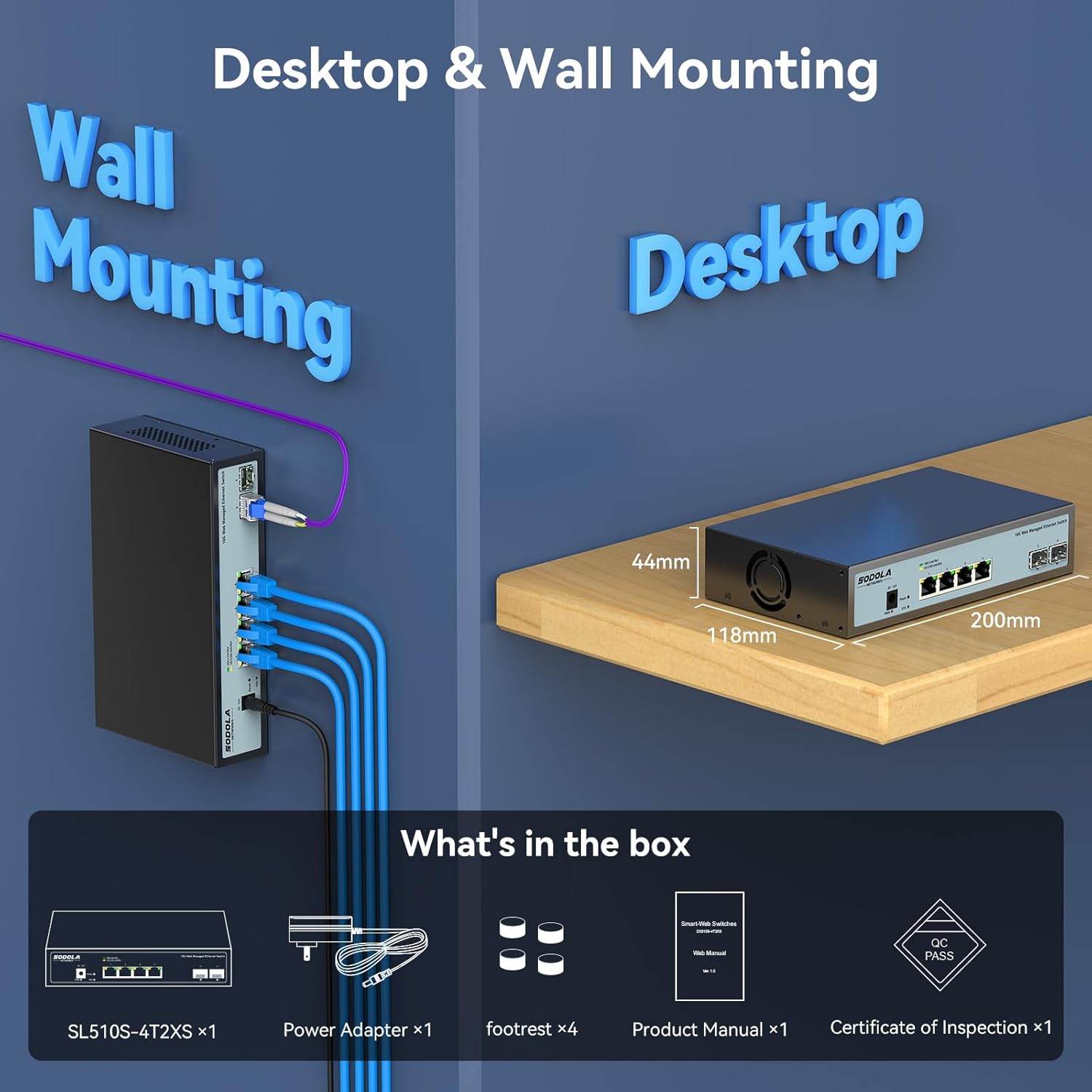
Figure 2: Included items: Switch, Power Adapter, Footrests, Product Manual, and Certificate of Inspection.
3. Koniec sprzętuview
3.1 Panel przedni
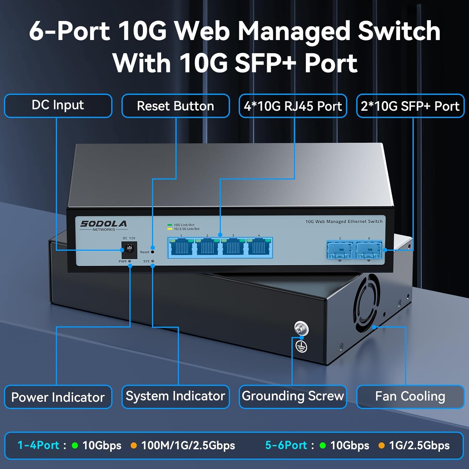
Rysunek 3: Układ panelu przedniego
Na panelu przednim znajdują się następujące elementy:
- Wejście DC: Port podłączenia zasilania.
- Przycisk resetowania: Służy do przywracania ustawień fabrycznych urządzenia.
- 4 x 10G RJ45 Ports: Adaptive ports supporting 100M/1G/2.5G/5G/10G speeds.
- 2 porty 10G SFP+: Support manual switching between 10G/1G/100M or 2.5G/1G/100M adaptive.
- Wskaźnik zasilania: Wskazuje stan zasilania.
- Wskaźnik systemu: Wskazuje stan operacyjny systemu.
3.2 Panel tylny
The rear panel includes a grounding screw and fan cooling vents.
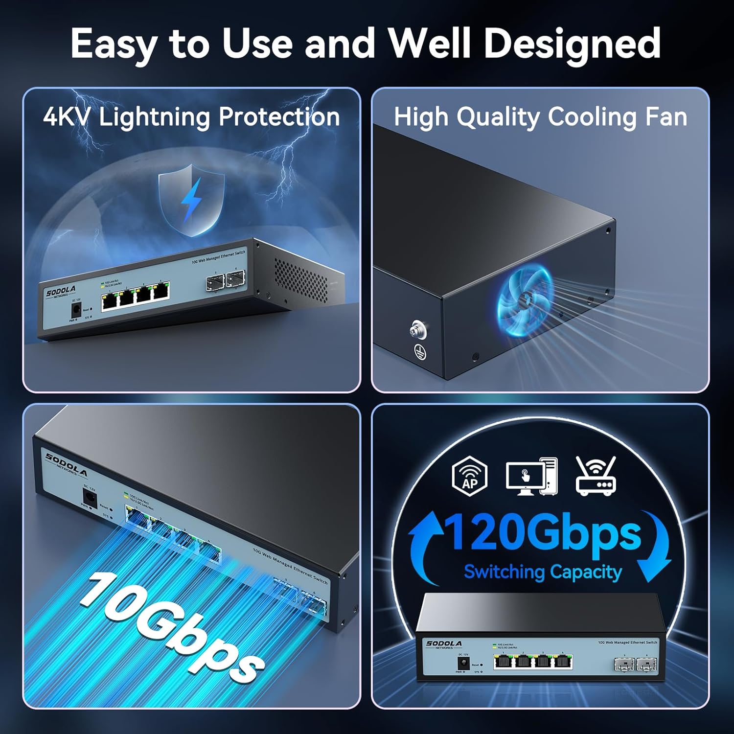
Figure 4: Rear Panel with Cooling Fan and Grounding Screw
- Śruba uziemiająca: For proper electrical grounding.
- Chłodzenie wentylatorowe: Internal cooling fan for heat dissipation.
4. Konfiguracja
4.1 Fizyczna instalacja
The switch supports both desktop and wall mounting. Choose a stable, well-ventilated location for installation.

Figure 5: Desktop and Wall Mounting Options
4.2 Podłączanie przełącznika
- Connect the power adapter to the DC input port on the switch and plug it into a power outlet.
- Connect your network devices (e.g., computers, servers, NAS, routers) to the RJ45 or SFP+ ports using appropriate Ethernet cables or SFP+ transceivers.
- Ensure proper grounding by connecting a grounding wire to the grounding screw.
Video 1: This video demonstrates the basic plug-and-play setup for a 10G Ethernet switch, showing connections to various network devices. While it features an unmanaged switch, the physical connection steps are similar.
5. Obsługa Web Managed Interface
This switch features a web-based management interface for advanced configuration. To access it, follow these steps:
- Initial IP Configuration: Before logging in, you must set an IP address via IPv4 on your computer to match the switch's default subnet. The default IP address for the switch is typically 192.168.2.1.
- Accessing the Interface: Otwórz web przeglądarki i wprowadź domyślny adres IP przełącznika (np. http://192.168.2.1) na pasku adresu.
- Login: Enter the default credentials. The default username is administracja, and there is typically no default password (leave it blank).

Rysunek 6: Łatwy Web Managed Method for Initial Access
5.1 Key Management Features
Ten web interface provides access to various features for network control and monitoring:
- Ustawienia portu: Configure individual port speeds (auto-negotiation is recommended for RJ45 ports), enable/disable ports, and manage flow control. For SFP+ ports, manual speed setting may be required for 2.5G or 1G devices.
- VLAN Management: Create and manage Virtual Local Area Networks for network segmentation.
- Agregacja łączy (LACP): Połącz wiele łączy fizycznych w jedno łącze logiczne, aby uzyskać większą przepustowość i redundancję.
- Jakość usług (QoS): Nadaj priorytet ruchowi sieciowemu dla krytycznych aplikacji.
- Kontrola burzy: Prevent network disruptions caused by broadcast, multicast, or unknown unicast storms.
- Dublowanie portów: Monitoruj ruch sieciowy, wysyłając kopię pakietów z jednego portu do drugiego.
- Śledzenie DHCP: Enhance network security by filtering untrusted DHCP messages.
- SNMP: Monitoruj urządzenia sieciowe ze stacji centralnego zarządzania.
- RSTP (protokół szybkiego drzewa rozpinającego): Zapobiegaj powstawaniu pętli sieciowych.

Rysunek 7: Koniecview of Web Funkcje zarządzania
Video 2: This video provides a demonstration of the web management interface, including login and basic configuration steps for a similar 10G managed switch. It highlights how to navigate and apply settings.
Wideo 3: Overview of a 10G web managed SFP+ switch, demonstrating its features and management capabilities. This can help users understand the interface and available options.
5.2 Zapisywanie konfiguracji
After making any changes in the web interface, it is crucial to save the configuration to ensure your settings are retained after a reboot or power cycle. Navigate to the "Maintenance" or "System" section and select "Save Configuration" or a similar option, then apply the changes.

Figure 8: Remember to Save Configuration
6. Konserwacja
6.1 Wentylator chłodzący
The switch is equipped with an internal cooling fan to manage heat dissipation. If fan noise is a concern, the fan can be removed by opening the case. Ensure the device remains in a well-ventilated area if the fan is removed.
6.2 aktualizacji oprogramowania sprzętowego
Okresowo sprawdzaj producenta website for firmware updates to ensure optimal performance and access to the latest features and security enhancements. Follow the instructions provided with the firmware update package for proper installation.
7. Rozwiązywanie Problemów
- Brak zasilania: Ensure the power cord is securely connected to the switch and a working power outlet. Check the power indicator LED.
- Brak łącza/aktywności na porcie:
- Verify the Ethernet cable is correctly connected to both the switch and the network device.
- Check the link/activity LED for the specific port.
- Sprawdź, czy podłączone urządzenie jest włączone i działa prawidłowo.
- For SFP+ ports, confirm the SFP+ module is properly inserted and compatible.
- W web interface, check the port status and ensure it is enabled and configured for the correct speed (especially for SFP+ ports).
- Nie można uzyskać dostępu Web Interfejs:
- Ensure your computer's IP address is in the same subnet as the switch's default IP (e.g., 192.168.2.x).
- Clear your browser's cache.
- Spróbuj innego web przeglądarka.
- If you have changed the switch's IP address and forgotten it, you may need to perform a factory reset using the reset button.
- Niska prędkość sieci:
- Verify that all connected devices and cables support 10G speeds for optimal performance.
- Check port speed settings in the web interface; ensure auto-negotiation is enabled for RJ45 ports or the correct speed is manually set for SFP+ ports.
- Inspect cables for damage or improper termination.
8. Specyfikacje
| Funkcja | Szczegół |
|---|---|
| Model | 4x10G RJ45+2x10G SFP+ (Managed) |
| Typ interfejsu | 4 x 10G Base-T Ports + 2 x 10G SFP+ Ports |
| Szybkość przesyłu danych | 10 gigabitów na sekundę |
| Liczba portów | 6 |
| Materiał obudowy | Metal |
| Waga przedmiotu | 2.05 funta |
| Wymiary opakowania | 12.09 x 7.64 x 2.44 cala |
| Kolor | Czarny |
| Kompatybilne urządzenia | Desktop, Laptop, Router |
9. Gwarancja i wsparcie
SODOLA offers a one-year free replacement for any non-human-induced quality issues and lifetime technical support. For assistance, please contact Sodola Networks customer service.
Aby uzyskać więcej informacji i wsparcia, odwiedź stronę Sodola Store on Amazon.