1. Wprowadzenie
This manual provides comprehensive instructions for the installation, operation, and maintenance of the Danfoss MCX06D Programmable Controller. Please read this manual thoroughly before using the device to ensure safe and efficient operation. This controller is designed for advanced industrial applications requiring precise control and communication capabilities.
2. Koniec produktuview
The Danfoss MCX06D is a versatile programmable controller featuring 6 relays, designed for 24V systems. It supports multiple communication protocols including CANBUS, MODBUS, and RS485, making it suitable for integration into various industrial control systems.
2.1 Główne cechy
- 6 Relays for flexible output control.
- 24V power supply compatibility.
- Multiple communication interfaces: CANBUS, MODBUS, RS485.
- Robust design for industrial environments.
- Model Number: 080G0112.
2.2 składniki produktu
The MCX06D controller includes the main unit with integrated display and control buttons, various input/output terminals, and communication ports.
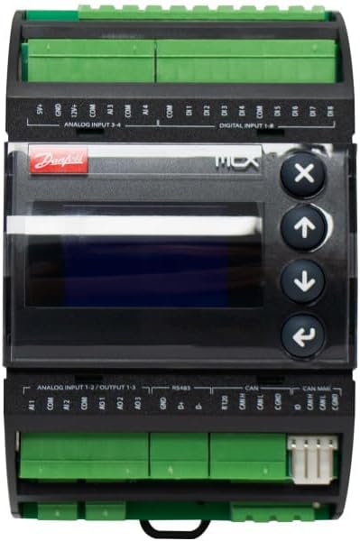
Rycina 2.2.1: Przód view of the Danfoss MCX06D Programmable Controller. This image displays the main unit with its central display screen, four control buttons (X, Up, Down, Back), and clearly labeled green terminal blocks for analog inputs, digital inputs, and communication ports (RS485, CAN).

Rysunek 2.2.2: Widok z góry na dół view of the Danfoss MCX06D Programmable Controller. This image highlights the upper section of the controller, detailing the green terminal blocks for analog inputs (S+, GND, AI1, AI2, AI3, AI4) and digital inputs (DI1 through DI8), along with their common (COM) connections.

Rysunek 2.2.3: Od dołu do góry view of the Danfoss MCX06D Programmable Controller. This image shows the lower section of the controller, focusing on the green terminal blocks for power input (IN, POWER, L, S, SYNC), digital outputs (NO1 through NO6, C1 through C6), and communication interfaces (RS485, CAN, CAN MMI).

Rysunek 2.2.4: Strona view of the Danfoss MCX06D Programmable Controller. This image provides a profile view of the device, emphasizing its compact form factor and the arrangement of the terminal blocks on the top and bottom.

Rysunek 2.2.5: Tył view of the Danfoss MCX06D Programmable Controller. This image displays the back of the unit, showing the mounting clips or rails for installation within an enclosure or panel.

Rysunek 2.2.6: Kątowy view of the Danfoss MCX06D Programmable Controller. This perspective provides a comprehensive look at both the upper and lower terminal blocks, as well as the central display and control buttons, offering a good overall view of the device's layout.

Figure 2.2.7: Danfoss MCX06D Programmable Controller in its retail packaging. This image shows the controller resting on its white cardboard box, which features the Danfoss logo and product details such as "Electronic controller MCX06D 080G0112 24V AC/20-60V DC, LCD".
3. Konfiguracja i instalacja
Proper installation is crucial for the reliable operation of the MCX06D controller. Ensure all safety precautions are followed during installation.
3.1 Środki ostrożności
- Odłącz zasilanie przed instalacją lub konserwacją.
- Instalację powinien wykonywać wyłącznie wykwalifikowany personel.
- Zapewnij prawidłowe uziemienie.
- Unikaj narażania na działanie wilgoci i ekstremalnych temperatur.
3.2 Montaż
The MCX06D controller is designed for DIN rail mounting or screw mounting within an electrical enclosure. Ensure adequate ventilation around the unit.
3.3 połączeń przewodów
Refer to the wiring diagrams below for correct connection of power, inputs, outputs, and communication lines.
3.3.1 Power Supply (24V)
Connect the 24V AC/DC power supply to the designated terminals. Observe polarity for DC connections.
3.3.2 wejścia analogowe
Connect analog sensors (e.g., temperature, pressure) to the AI terminals. Ensure correct sensor type and wiring configuration (e.g., 0-10V, 4-20mA).
3.3.3 wejść cyfrowych
Connect digital signals (e.g., switches, relays) to the DI terminals. These inputs are typically used for on/off states or pulse counting.
3.3.4 wyjścia przekaźnikowe
The 6 relays provide configurable outputs for controlling external devices. Connect loads according to their power requirements and the relay specifications.
3.3.5 Communication Ports (CANBUS, MODBUS, RS485)
Connect communication cables to the respective ports. Ensure proper termination and addressing for network communication.
- RS485: Connect A and B lines. Ensure proper biasing and termination resistors if required by the network.
- Magistrala CAN: Connect CAN_H and CAN_L lines. Ensure proper termination resistors at the ends of the bus.
- MODBUS: Typically uses RS485 physical layer. Configure device address and baud rate in software.
4. Instrukcja obsługi
This section details the basic operation of the MCX06D controller, including navigation and parameter adjustment.
4.1 Początkowe włączenie zasilania
Upon initial power-up, the controller will perform a self-test and display the current firmware version. The default screen will then appear, typically showing system status or a main menu.
4.2 Navigation and Menu Structure
The controller features a display and four navigation buttons:
- Strzałka w górę: Navigates up in menus or increases parameter values.
- Strzałka w dół: Navigates down in menus or decreases parameter values.
- Enter/Confirm (Right Arrow): Wybiera opcję lub potwierdza ustawienie.
- Escape/Back (X button): Powrót do poprzedniego menu lub anulowanie operacji.
4.3 Regulacja parametrów
To adjust a parameter:
- Navigate to the desired parameter using the Up/Down arrows.
- Press the Enter button to select the parameter for editing.
- Use the Up/Down arrows to change the value.
- Press the Enter button to save the new value.
- Press the Escape button to exit the editing mode without saving, or to return to the previous menu.
4.4 Programowanie i konfiguracja
Advanced programming and configuration of the MCX06D controller are typically performed using dedicated Danfoss software tools connected via the communication ports. Refer to the software's user manual for detailed programming instructions.
5. Konserwacja
The Danfoss MCX06D controller is designed for minimal maintenance. However, periodic checks can ensure long-term reliability.
5.1 Czyszczenie
- Do czyszczenia zewnętrznej części urządzenia używaj miękkiej, suchej szmatki.
- Nie należy używać środków czyszczących o właściwościach ściernych ani rozpuszczalników.
- Ensure the unit is powered off before cleaning.
5.2 aktualizacji oprogramowania sprzętowego
Periodically check the Danfoss website for firmware updates. Firmware updates can provide new features, performance improvements, or bug fixes. Follow the instructions provided with the firmware update package carefully.
5.3 Sprawdzanie połączeń
Periodically inspect all wiring connections for tightness and signs of corrosion. Loose connections can lead to intermittent operation or system failures.
6. Rozwiązywanie Problemów
This section provides guidance for common issues encountered with the MCX06D controller.
| Problem | Możliwa przyczyna | Rozwiązanie |
|---|---|---|
| Kontroler nie włącza się. | Brak zasilania; Nieprawidłowe okablowanie; Przepalony bezpiecznik. | Check 24V power supply; Verify wiring connections; Check for internal or external fuses. |
| Display is blank or shows error code. | Firmware issue; Hardware fault; Power instability. | Perform a power cycle; Consult the specific error code in the detailed technical manual; Ensure stable power supply. |
| Communication failure (CANBUS/MODBUS/RS485). | Incorrect wiring; Incorrect address/baud rate; Missing termination resistors; Bus conflict. | Verify communication wiring; Check device address and baud rate settings; Ensure proper bus termination; Isolate devices to identify conflicts. |
| Relay outputs not activating. | Incorrect programming; Overload; Faulty relay. | Check programming logic; Verify load current; Contact support if relay is suspected faulty. |
If the problem persists after attempting these solutions, please contact Danfoss technical support.
7. Specyfikacje
Detailed technical specifications for the Danfoss MCX06D Programmable Controller.
- Model: 080G0112
- Zasilanie: 24V AC / DC
- Przekaźniki: 6
- Komunikacja: CANBUS, MODBUS, RS485
- Waga przedmiotu: 10.6 uncji (0.30 kg)
- Wymiary produktu: 7 x 9 x 5 cala (17.78 x 22.86 x 12.7 cm)
- Tom: 0.18 FTQ
- Producent: Danfoss
- ASIN: B0DLBM7RPL
- UPC-EAN: 5702423285372
- Data pierwszej dostępności: 29 października 2024 r.
8. Gwarancja i wsparcie
8.1 Informacje o gwarancji
Danfoss products are covered by a standard manufacturer's warranty. For specific warranty terms and conditions, please refer to the documentation included with your purchase or visit the official Danfoss website. Typically, this covers defects in materials and workmanship under normal use.
8.2 Wsparcie techniczne
For technical assistance, troubleshooting, or inquiries regarding the Danfoss MCX06D Programmable Controller, please contact Danfoss customer support. Contact information can be found on the official Danfoss webstronie lub w dokumentacji produktu.
Zasoby internetowe: Visit the official Danfoss website for product documentation, FAQs, and software downloads.
Informacje kontaktowe: Refer to your regional Danfoss support details for phone numbers and email addresses.


