
1. Wprowadzenie
This manual provides instructions for the installation, operation, and maintenance of your TOPBULL 60A MPPT Solar Charge Controller. This intelligent regulator is designed to efficiently manage power flow from solar panels to various battery types, ensuring optimal charging and system protection. Please read this manual thoroughly before installation and use.
2. Główne cechy
- Zaawansowana technologia MPPT: Achieves up to 99% tracking efficiency and 98% peak conversion efficiency for maximum power harvest from solar panels.
- Automatyczna objętośćtage Rozpoznawanie: Automatycznie wykrywa napięcie systemu 12 V lub 24 V DCtage.
- Szeroka kompatybilność baterii: Supports various deep cycle battery types including Sealed, Gel, Flooded (FLD), Lithium Iron Phosphate (LiFePO4), and AGM batteries. Includes 0V Li-ion battery charging (activation) support.
- Comprehensive Electronic Protections: Built-in safeguards against reverse polarity, battery overcharge, battery overdischarge, overload, short-circuit, TVS lightning, overpower, over-temperature, and reverse current.
- Intuicyjny wyświetlacz LCD: Provides real-time solar charging and battery operation information, customizable parameters, and error codes.
- Podwójne porty USB: Conveniently charge electronic devices (5V, 2.4A total).
- Efektywne odprowadzanie ciepła: Features a durable metal casing and dual high-speed intelligent fans for optimal thermal management, enhancing longevity and performance.
- Kompensacja temperatury: Automatically adjusts charging and discharging parameters based on ambient temperature to prolong battery life.
3. Koniec produktuview
Familiarize yourself with the components and display of the solar charge controller.

Rysunek 3.1: Przód view of the TOPBULL 60A MPPT Solar Charge Controller, showing the LCD display and control buttons.
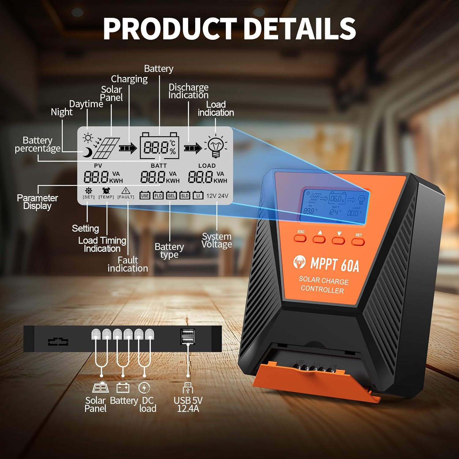
Rysunek 3.2: Detailed diagram illustrating the LCD display elements and the connection ports at the bottom of the controller. The display shows PV voltage, pojemność bateriitage, load status, battery percentage, and various indicators. The ports include connections for solar panel, battery, DC load, and dual USB 5V 2.4A outputs.
3.1. Wskaźniki wyświetlacza LCD
- PV (Photovoltaic): Wyświetla objętość panelu słonecznegotage i moc.
- BATT (Battery): Pokazuje poziom naładowania bateriitage, charge status, and type.
- ZAŁADUJ: Indicates load status and power consumption.
- Procent bateriitage: Wizualna reprezentacja poziomu naładowania baterii.
- Objętość systemutage: Displays 12V or 24V system recognition.
- Wyświetlanie parametrów: Shows current settings and values.
- Wskazanie błędu: Alerts for system errors.
3.2. Przyciski sterujące
- ESC: Used to switch load (manual switch) and exit setup menus.
- Strzałka w górę (▲): Navigates up through main interface pages to view parameters; increases values in setup mode.
- Strzałka w dół (▼): Navigates down through main interface pages to view parameters; decreases values in setup mode.
- ZESTAW: Enters setting mode, confirms selections, and saves changes. If no key operation for 10 seconds, it exits setting mode automatically.
4. Instalacja i konfiguracja
4.1. Środki ostrożności
- Przed podłączeniem zasilania należy upewnić się, że wszystkie połączenia są prawidłowe i bezpieczne.
- Zawsze podłączaj najpierw akumulator, potem panel słoneczny, a na końcu obciążenie. Odłączaj w odwrotnej kolejności.
- Zainstaluj kontroler w dobrze wentylowanym pomieszczeniu, z dala od materiałów łatwopalnych i bezpośredniego światła słonecznego.
- Aby zapobiec przegrzaniu, do wszystkich połączeń należy stosować przewody o odpowiednim przekroju.
4.2. Montaż kontrolera
Mount the controller vertically on a flat, non-flammable surface using the provided mounting screws. Ensure adequate clearance around the unit for proper airflow and heat dissipation, especially for the cooling fans located on the top.

Rysunek 4.1: Image showing the dimensions of the controller (approximately 9.0 inches long, 7.3 inches wide, 2.8 inches high) and the included mounting screws and user manual.
4.3. Połączenia okablowania
Follow the connection order carefully to avoid damage to the controller or other components.
- Podłącz akumulator: Connect the positive and negative terminals of your battery bank to the corresponding battery terminals on the controller. The controller will automatically detect the system voltage (12 V lub 24 V).
- Podłącz panel słoneczny: Connect the positive and negative leads from your solar panel array to the solar panel terminals on the controller. Ensure the maximum PV input voltage does not exceed 100VDC. For a 12V system, maximum solar input power is 720W; for a 24V system, it is 1440W.
- Podłącz obciążenie DC (opcjonalnie): Connect your DC loads to the load terminals on the controller. This allows the controller to manage load discharge and provide protection.

Rysunek 4.2: Wiring diagram illustrating the correct connection sequence: Battery first, then Solar Panel, then DC Load. An optional inverter for AC loads is also shown connected to the battery bank.
4.4. Wybór typu baterii
The controller is compatible with various battery types. It is crucial to select the correct battery type for optimal charging and battery longevity. Refer to the display and settings section to adjust this parameter if needed. The controller supports FLD (Flooded), LiFePO4 (Lithium Iron Phosphate), SLD (Sealed Lead-Acid), GEL, and AGM batteries.

Rysunek 4.3: Illustration showing the controller connected to a battery, with icons representing compatible battery types: LI (Lithium), FLD (Flooded), GEL, SLD (Sealed), and AGM. The controller automatically identifies battery voltage and supports custom parameters, including lithium battery 0V charging.
5. Działanie
5.1. Monitorowanie wyświetlacza
The LCD display provides real-time information about your solar system. Use the Up (▲) and Down (▼) buttons to cycle through different display screens, showing parameters such as PV voltage, pojemność bateriitage, charging current, load current, and battery state of charge.
5.2. Ustawienia parametrów
To enter the parameter setting stage:
- Press the "SET" button to enter the setting mode. The value to be adjusted will flash.
- Use the Up (▲) or Down (▼) buttons to adjust the value.
- Press the "SET" button again to confirm and save the new value.
If no button is pressed for 10 seconds in setting mode, the controller will automatically exit without saving changes.
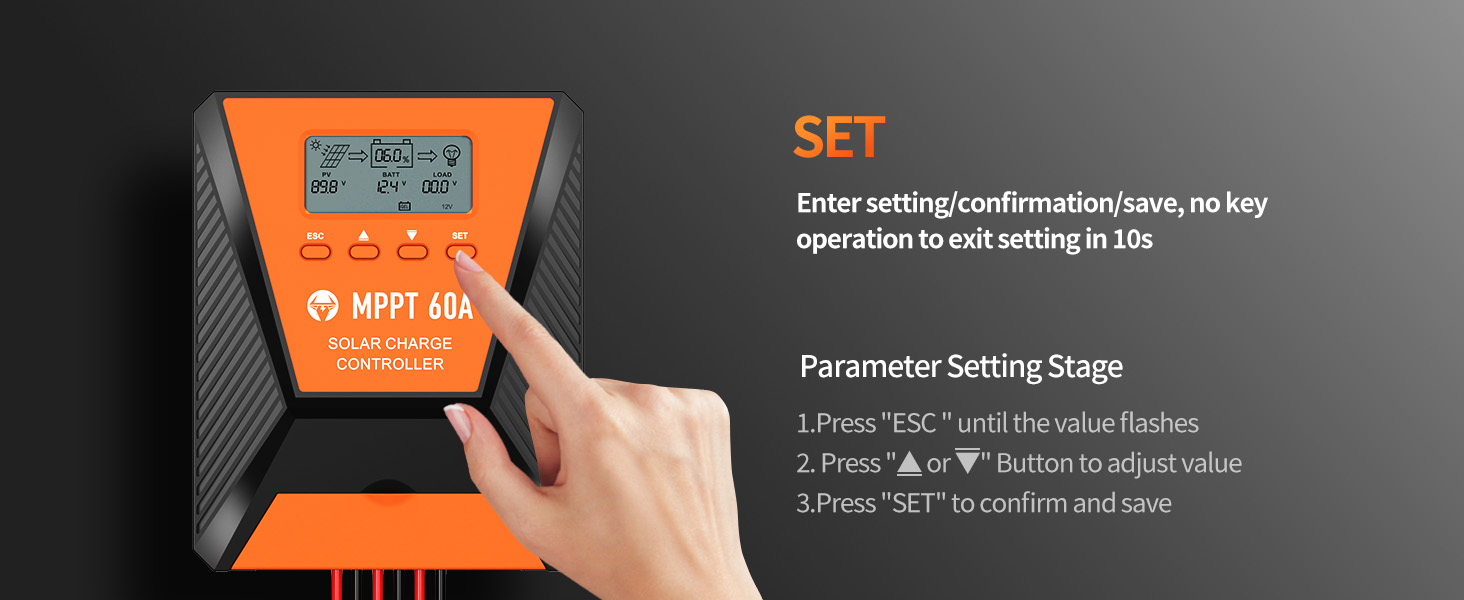
Rysunek 5.1: Visual guide for using the SET button to enter, adjust, and confirm parameter settings on the controller's LCD display.
5.3. Załaduj tryby pracy
The controller supports three distinct load working modes:
- Lighting Time Control Mode (1H-23H): The load automatically turns on or off based on the intensity of sunlight and a set timer.
- Normal OFF Mode (0H): The load remains off. This mode is useful for specific loads or during debugging.
- Normal ON Mode (24H): The load remains continuously on. This mode is suitable for loads requiring a 24-hour power supply.

Rysunek 5.2: Diagram explaining the three load working modes: Lighting time control (1H-23H), Normal OFF (0H), and Normal ON (24H).
6. Konserwacja
Regularna konserwacja zapewnia długowieczność i optymalną wydajność regulatora ładowania słonecznego.
- Sprawdź połączenia: Okresowo sprawdzaj wszystkie połączenia przewodów pod kątem szczelności i korozji. Luźne połączenia mogą powodować opór i nagrzewanie się.
- Wyczyść kontroler: Keep the controller clean and free from dust and debris. Ensure the cooling fan vents are unobstructed. Use a dry cloth for cleaning.
- Monitoruj wydajność: Regularly check the LCD display for normal operation and any error codes. Compare actual performance with expected values.
- Kontrola baterii: Inspect battery terminals for corrosion and ensure proper ventilation around the batteries.
7. Rozwiązywanie Problemów
W tej sekcji omówiono typowe problemy, jakie mogą wystąpić podczas korzystania z regulatora ładowania słonecznego.
| Problem | Możliwa przyczyna | Rozwiązanie |
|---|---|---|
| Brak wyświetlacza/Kontroler nie włącza się | Akumulator nie jest podłączony lub jego głośność jest niskatage; reverse polarity; loose wiring. | Sprawdź połączenia akumulatora i objtage. Ensure correct polarity. Tighten all wiring. |
| Bateria się nie ładuje | Solar panel not connected; insufficient sunlight; solar panel fault; incorrect battery type setting. | Verify solar panel connections. Ensure adequate sunlight. Check solar panel output. Confirm correct battery type setting. |
| Ładowanie nie działa | Load disconnected; overload protection activated; incorrect load working mode. | Check load connections. Reduce load to within controller limits. Adjust load working mode settings. |
| Wyświetlony kod błędu | Specific system fault (e.g., over-temperature, short-circuit). | Refer to the controller's display for the specific error code and consult the full user manual for detailed explanations and solutions. Address the underlying issue (e.g., reduce temperature, clear short-circuit). |
8. Specyfikacje
| Parametr | Wartość |
|---|---|
| Model | 60A |
| Objętość systemutage | Automatyczne rozpoznawanie 12 V / 24 V. |
| Maks. Wejście PV Objętośćtage | 100 V prądu stałego |
| Maksymalna moc wejściowa energii słonecznej (system 12 V) | 720 W |
| Maksymalna moc wejściowa energii słonecznej (system 24 V) | 1440 W |
| Wydajność śledzenia | ≥99% |
| Maksymalna wydajność konwersji | Do 98% |
| Obsługiwane typy baterii | FLD, LiFePO4, SLD, GEL, AGM |
| Wyjście USB | Dual 5V, 2.4A (Total) |
| Wymiary (w przybliżeniu) | 10.71 x 8.62 x 4.33 cala (opakowanie) |
| Waga przedmiotu | 3.36 funta |
| Tworzywo | Metal |
| Typ wyświetlacza | LCD |
9. Gwarancja i wsparcie
TOPBULL products are designed for reliability and performance. For warranty information or technical assistance, please contact TOPBULL customer support through the retailer where the product was purchased or visit the official TOPBULL webStrona. Kontaktując się z pomocą techniczną, prosimy o przygotowanie numeru modelu produktu i daty zakupu.
Aby uzyskać więcej informacji, odwiedź stronę TOPBULL Store on Amazon.