1. Wprowadzenie
This manual provides detailed instructions for the installation, operation, and maintenance of your STINGER Audio MT20001 Monoblock Class D Car Amplifier. The MT20001 is designed to deliver high-efficiency power for subwoofer systems in car audio applications, ensuring optimal sound quality. Please read this manual thoroughly before installation and use to ensure proper function and safety.
2. Informacje dotyczące bezpieczeństwa
Zawsze należy przestrzegać następujących środków ostrożności, aby zapobiec obrażeniom lub uszkodzeniom amplifier lub pojazd:
- Odłącz akumulator pojazdu: Before beginning any installation, disconnect the vehicle's negative battery terminal to prevent electrical shorts.
- Zalecana profesjonalna instalacja: If you are unsure about the installation process, consult a qualified car audio professional.
- Prawidłowe okablowanie: Use appropriate gauge wiring as specified in this manual. Incorrect wiring can lead to overheating, fire, or damage to components.
- Wentylacja: Zapewnij amplifier is mounted in a location with adequate airflow to prevent overheating. Do not block cooling fins.
- Bezpieczne mocowanie: Zamontuj ampZamocuj go bezpiecznie, aby zapobiec jego poluzowaniu się podczas jazdy pojazdem, co mogłoby spowodować obrażenia lub uszkodzenia.
- Unikaj wilgoci: Nie wystawiaj na działanie amplifier to moisture or water. This product is not waterproof.
- Zabezpieczenie bezpiecznika: Always use the correct fuse rating as specified. Never replace a fuse with one of a higher rating.
3. Zawartość opakowania
Sprawdź, czy w przesyłce znajdują się wszystkie elementy:
- STINGER Audio MT20001 Monoblock Class D Ampżywsze
- Remote Subwoofer Level Control with cable
- STINGER 4-Gauge Copper Amplifier Wiring Kit, including:
- 17FT Translucent Blue Power Wire
- 3FT Translucent Silver Ground Wire
- 17FT Translucent Blue Twisted Pair RCA interconnects
- 16FT Blue Remote Turn-on Wire
- 20FT Translucent Speaker Wire
- 3FT Black flex loom tubing
- 1pc Mini-ANL/AFS Fuseholder & Fuse
- Sprzęt montażowy (śruby)
- Instrukcja obsługi (ten dokument)

Image: STINGER 1200W Amplifier Wiring Kit packaging, showing the various cables and fuse holder included.
4. Funkcje produktu
The STINGER Audio MT20001 amplifier incorporates advanced design and technology for superior performance:
- Digital Class-D Monoblock Design: High efficiency with a compact footprint, optimized for subwoofer applications.
- Robust Unregulated Power Supplies: Utilizes advanced pulse width modulator integrated circuits for improved performance and efficiency.
- Direct Insert Terminals: Features 0/1 Gauge Power and 8 Gauge Speaker direct insert terminals for secure connections.
- Szerokie pasmo przenoszenia: 10Hz-180Hz, suitable for deep bass reproduction.
- Zdalna kontrola poziomu subwoofera: Included for convenient bass level adjustments.
- Precision Metal Potentiometers: For accurate tuning of audio settings.
- Designed for 1 Ohm Load: Capable of driving demanding subwoofer configurations.

Obraz: Góra view of the STINGER MT-2000.1 amplifier, with text overlays indicating features such as small footprint, 2000W @ 1 Ohm, direct insert terminals, 0/1 gauge power, 8 gauge speaker, 10Hz-180Hz frequency response, and included bass knob.

Image: STINGER MT-2000.1 amplifier, labeled as Class-D Mono Block, with icons and text indicating it's designed for 1 Ohm load, has a small and compact design, features 0/1 Gauge Power Terminal, has a Bridged RMS Rating of 3,800W / 2 Ohm Minimum, and an Operating voltage od 9 V do 16 V.
5. Konfiguracja i instalacja
Careful installation is crucial for optimal performance and safety. Follow these steps for proper setup.
5.1 Identyfikacja komponentów
Zapoznaj się z amplifier's input and output terminals and control panel:

Obraz: Tył view of the STINGER MT-2000.1 amplifier showing the control panel. Labels include PRT (Protection Indicator), PWR (Power Indicator), REMOTE port (for bass knob), INPUT RCA (L/R), BRIDGE IN RCA, GAIN knob (Min/Max), LPF knob (40Hz-180Hz), SUBSONIC knob (OFF/50Hz), FREQ knob (30Hz/80Hz), BOOST knob (0dB/12dB), and INPUT BRIDGE OUT RCA.
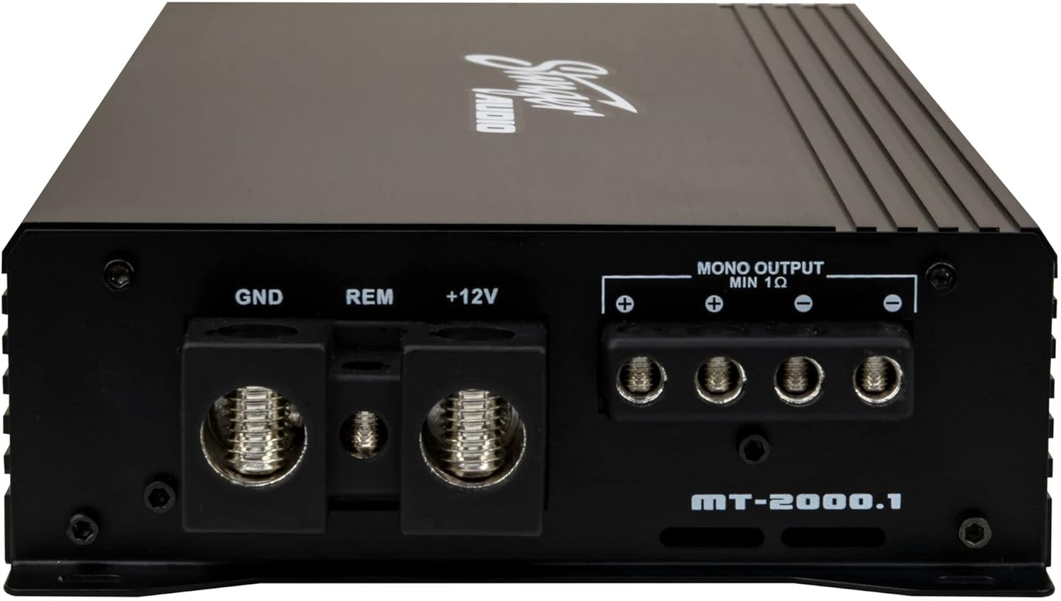
Obraz: Tył view of the STINGER MT-2000.1 amplifier showing the power and speaker terminals. Labels include GND (Ground), REM (Remote Turn-on), +12V (Power), and MONO OUTPUT MIN 1 Ohm speaker terminals (+ and -).
5.2 połączeń przewodów
Follow these steps for secure and correct wiring:
- Przewód zasilający (+12V): Connect the 17FT Translucent Blue Power Wire from the vehicle's positive battery terminal (via the Mini-ANL/AFS Fuseholder & Fuse, installed within 18 inches of the battery) to the +12V terminal on the amplifier. Ensure a secure, crimped connection.
- Przewód uziemiający (GND): Connect the 3FT Translucent Silver Ground Wire from the GND terminal on the amplifier to a clean, unpainted metal surface on the vehicle chassis. Ensure a solid, low-resistance connection.
- Remote Turn-on Wire (REM): Connect the 16FT Blue Remote Turn-on Wire from the REM terminal on the amplifier to the remote output of your head unit or other switched 12V source. This wire turns the ampwłączanie i wyłączanie projektora za pomocą jednostki głównej.
- Wejście RCA: Connect the 17FT Translucent Blue Twisted Pair RCA interconnects from the RCA output of your head unit to the INPUT RCA terminals (L/R) on the amplifier. For bridged input, use the BRIDGE IN RCA terminal.
- Wyjście głośnika: Connect your subwoofer(s) to the MONO OUTPUT MIN 1 Ohm terminals on the amplifier using the 20FT Translucent Speaker Wire. Observe correct polarity (+ to + and - to -). Ensure the total impedance of your subwoofer(s) is 1 Ohm or higher.
- Zdalna kontrola poziomu subwoofera: Plug the included remote bass knob into the REMOTE port on the ampliyfikator.
5.3 Montaż
Choose a mounting location that provides adequate ventilation and is secure. Avoid mounting the amplifier directly to carpet or in enclosed spaces without airflow. Use the provided mounting hardware to firmly attach the amplifier to a solid surface in your vehicle.
6. Instrukcja obsługi
Po zainstalowaniu dostosuj ampustawienia filtra zapewniające optymalną jakość dźwięku.
6.1 Regulacja elementów sterujących
- GAIN (Input Level): Ta kontrola pasuje do amplifier's input sensitivity to the output of your head unit. Start with the gain at minimum (fully counter-clockwise). Play a familiar track at about 75% of your head unit's maximum volume. Slowly increase the gain until you hear distortion, then back off slightly.
- LPF (filtr dolnoprzepustowy): This filter allows only frequencies below the set point to pass through to the subwoofer. Adjust this knob (40Hz-180Hz) to blend the subwoofer's output with your main speakers. A common starting point is 80Hz.
- PODDŹWIĘKOWY: This high-pass filter removes extremely low frequencies that are below the audible range or harmful to your subwoofer. Set it to OFF or 50Hz, depending on your subwoofer's capabilities and enclosure tuning.
- FREQ (Bass EQ Frequency): This knob (30Hz/80Hz) selects the center frequency for the Bass BOOST.
- BOOST (Bass EQ Level): This control (0dB/12dB) increases the output at the selected FREQ. Use sparingly to avoid distortion and potential damage to your subwoofer.
6.2 Remote Subwoofer Level Control
The included remote level control allows you to conveniently adjust the subwoofer output level from your driving position. This control only adjusts the output level and does not affect the ampustawienie wzmocnienia lifiera.

Image: The STINGER remote subwoofer level control, a small black box with a rotary knob labeled 'MIN' to 'MAX', connected by a cable.
7. Konserwacja
The STINGER MT20001 amplifier wymaga minimalnej konserwacji, aby zapewnić długotrwałą wydajność.
- Czyszczenie: Okresowo wycieraj ampZewnętrzną powierzchnię filtra czyścić miękką, suchą ściereczką. Nie używać silnych środków chemicznych ani ściernych środków czyszczących.
- Sprawdź połączenia: Annually, inspect all power, ground, remote, RCA, and speaker connections to ensure they are secure and free from corrosion. Loose connections can cause performance issues or damage.
- Wentylacja: Upewnij się, że amplifier's cooling fins remain clear of obstructions to maintain proper heat dissipation.
8. Rozwiązywanie Problemów
Jeśli masz problemy ze swoim amplifier, refer to the following table for common issues and solutions:
| Problem | Możliwa przyczyna | Rozwiązanie |
|---|---|---|
| Brak zasilania (dioda LED zasilania wyłączona) | Blown fuse, loose power/ground/remote wire, no 12V at battery. | Check fuse, verify all power connections, test battery voltage. |
| Tryb ochrony (dioda PRT włączona) | Overheating, speaker short circuit, low impedance load. | Ensure proper ventilation, check speaker wiring for shorts, verify speaker impedance is 1 Ohm or higher. Allow ampchłodzić. |
| Brak wyjścia dźwięku | No RCA signal, gain too low, speaker wires disconnected, head unit off. | Check RCA connections, adjust gain, verify speaker wiring, ensure head unit is on and playing audio. |
| Zniekształcony dźwięk | Gain set too high, poor ground connection, damaged speaker, incorrect LPF/BOOST settings. | Reduce gain, check ground connection, inspect speaker, adjust LPF/BOOST settings. |
| Amplifier przegrzewa się | Insufficient ventilation, impedance too low, gain too high. | Przenieść się amplifier for better airflow, verify speaker impedance, reduce gain. |
9. Specyfikacje
Detailed technical specifications for the STINGER Audio MT20001 Monoblock Class D Car AmpLiyfikator:
| Specyfikacja | Wartość |
|---|---|
| Nazwa modelu | MT20001 |
| Tworzywo | Metal |
| Typ głośnika | Subwoofer |
| Maksymalna moc wyjściowa głośnika | 2000 watów |
| Tryb wyjścia audio | Mononukleoza |
| Technologia łączności | RCA |
| Technologia łączności z subwooferem | Przewodowy |
| Metoda kontroli | Zdalny |
| Źródło zasilania | Elektryczny przewodowy |
| Objętość operacyjnatage | 9V do 16V |
| Minimalna impedancja | 1 omy |
| Typ montażu | Kołnierz płaski |
| jest wodoodporny | FAŁSZ |
| Numer modelu przedmiotu | MT20001 |
| Data pierwszej dostępności | 20 sierpnia 2024 r. |

Image: STINGER MT-2000.1 amplifier with dimensions indicated: 12.16 inches (309 mm) length, 6.1 inches (155 mm) width, and 2.09 inches (53 mm) height.
10. Gwarancja i wsparcie
STINGER products are designed for reliability and performance. For specific warranty information, please refer to the warranty card included with your product or visit the official STINGER website. If you encounter any issues not covered in this manual or require technical assistance, please contact STINGER customer support through their official channels.
STINGER Customer Support: Refer to your product packaging or the official STINGER webna tej stronie znajdziesz najbardziej aktualne dane kontaktowe.