POWLAND iCharger-MPPT-2420
Instrukcja obsługi regulatora ładowania słonecznego MPPT POWLAND 20A
Model: iCharger-MPPT-2420
1. Wprowadzenie
This manual provides detailed instructions for the installation, operation, and maintenance of the POWLAND 20A MPPT Solar Charge Controller. This device is designed to efficiently manage power flow from solar panels to various battery types, ensuring optimal charging and system longevity. It supports 12V and 24V battery systems with automatic voltage wykrywanie.

Figure 1: POWLAND 20A MPPT Solar Charge Controller (Model iCharger-MPPT-2420)
Na tym zdjęciu widać przód view of the POWLAND 20A MPPT Solar Charge Controller, featuring its white casing, blue control panel with an LCD screen, and two control buttons. The branding "EASUN POWER" and "MPPT Solar Charge Controller" are visible.
2. Główne cechy
- Technologia MPPT: Advanced Maximum Power Point Tracking (MPPT) ensures high tracking efficiency (up to 99%) and conversion efficiency (up to 98%) for optimal solar energy harvesting.
- Automatyczna objętośćtage Wykrywanie: Automatically detects 12V or 24V battery system voltage.
- Szeroka kompatybilność baterii: Suitable for a variety of battery types including User-defined, Lithium, Flooded, Sealed, and Gel batteries.
- Multi-stage Ładowanie: Posiada 3-stage charging process to optimize battery performance and extend lifespan.
- LCD Multifunction Display: Provides real-time operational data, system status, and allows for parameter adjustments.
- Solidna konstrukcja: Aluminum alloy heat dissipation shell minimizes loss during charging.
- Kompleksowa ochrona: Includes protection against reverse polarity of PV modules, battery reverse polarity, battery over-voltage, battery over-discharge, and overload.
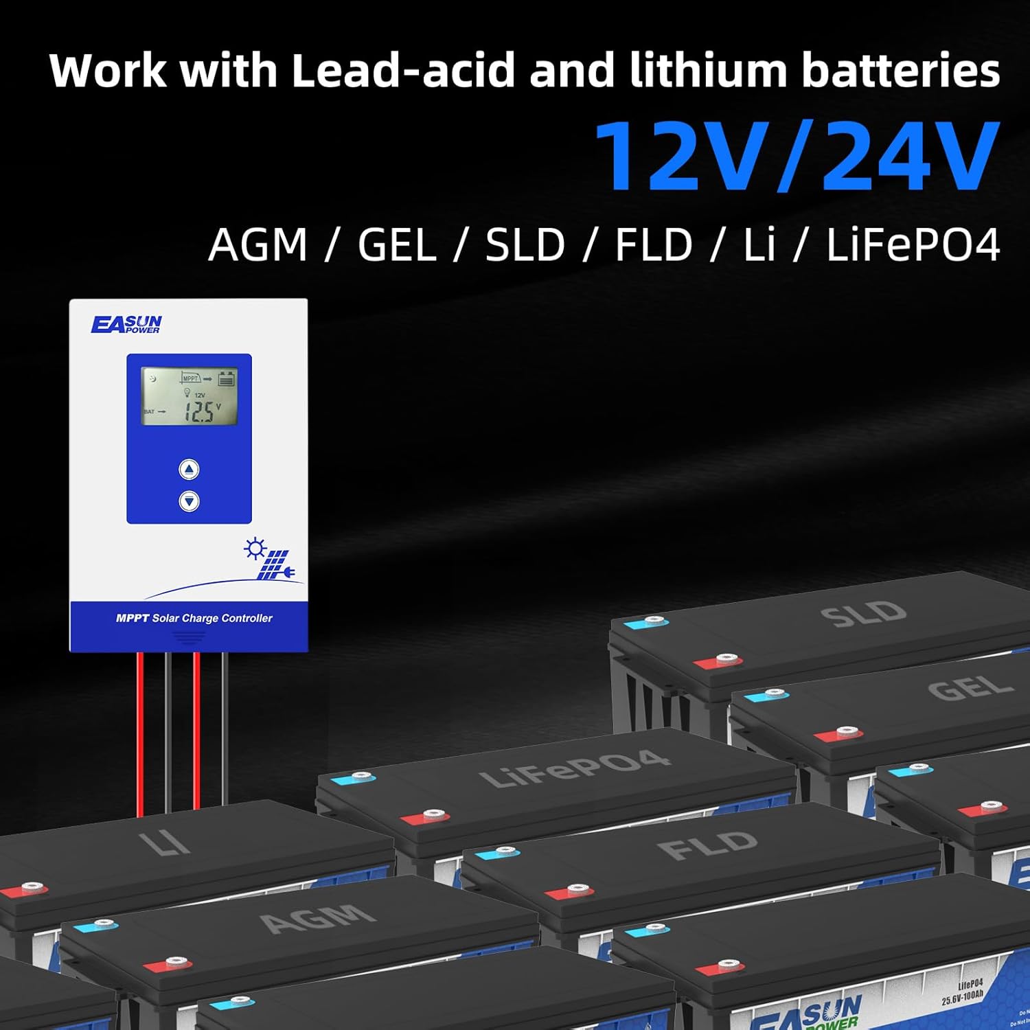
Figure 2: Compatibility with Lead-acid and Lithium Batteries
This image illustrates the controller's compatibility with various 12V/24V battery types, including AGM, GEL, SLD, FLD, Li (Lithium), and LiFePO4. Several battery packs are shown with the controller in the background.
3. Specyfikacje
| Specyfikacja | Wartość |
|---|---|
| Numer modelu | iCharger-MPPT-2420 |
| Prąd znamionowy ładowania | 20A |
| Objętość systemutage | Automatyczne rozpoznawanie 12 V / 24 V. |
| Maks. Objętość wejścia PVtage VOC) | 60 V |
| Maksymalna moc wejściowa PV (system 12 V) | 260 W |
| Maksymalna moc wejściowa PV (system 24 V) | 520 W |
| PV CztagZasięg (system 12 V) | 16.8-60 V |
| PV CztagZasięg (system 24 V) | 33.6-60 V |
| Znamionowy prąd rozładowania | 20A |
| Obsługiwane typy baterii | User, Lithium, Flooded, Sealed, Gel |
| Wydajność śledzenia | 99% |
| Efektywność konwersji | 98% |
| Wymiary produktu | Wymiary 17.8 x 12.4 x 4.8 cm |
| Waga przedmiotu | 0.6 kilograma |
| Typ wyświetlacza | LCD |

Figure 3: Detailed MPPT Controller Specifications
This image presents a table detailing the specifications for MPPT controllers, including rated charge current, solar panel input voltage, maximum solar power input, system rated voltage, rated discharge current, battery types, and physical dimensions for models iCharger-MPPT-2420, iCharger-MPPT-2430, and iCharger-MPPT-2440.
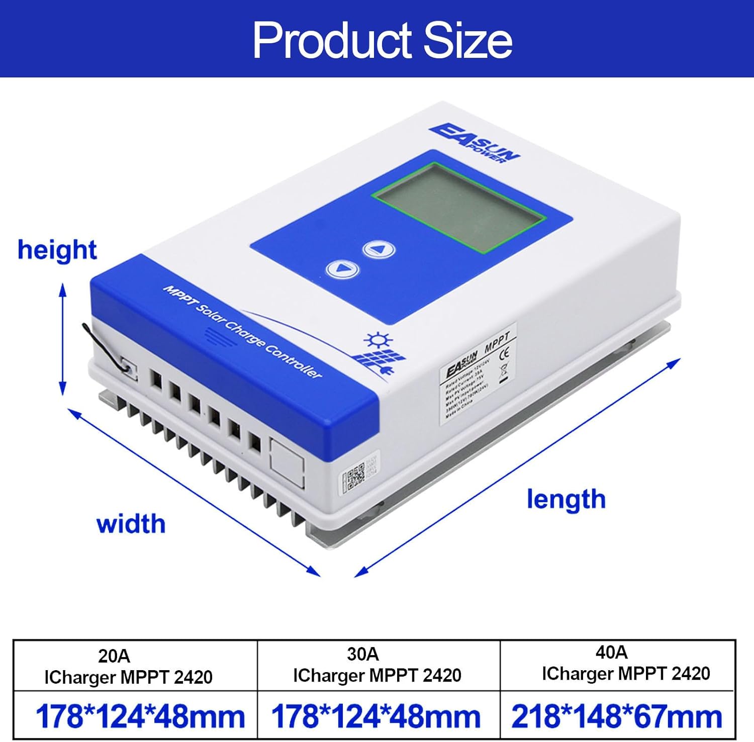
Rysunek 4: Wymiary produktuview
This diagram illustrates the height, width, and length of the MPPT Solar Charge Controller, with a table below providing specific dimensions for the 20A (iCharger MPPT 2420), 30A, and 40A models.
4. Konfiguracja i instalacja
Prawidłowa instalacja jest kluczowa dla bezpiecznego i wydajnego działania regulatora ładowania słonecznego. Prosimy o dokładne przestrzeganie poniższych kroków:
- Najpierw podłącz akumulator: Zawsze podłączaj akumulator do regulatora ładowania przed podłączeniem panelu słonecznego. Upewnij się, że biegunowość jest prawidłowa (+ do + i - do -).
- Podłącz obciążenie DC (opcjonalnie): If you have a DC load, connect it to the controller's load terminals. If no DC load is used, this step can be skipped.
- Podłącz panel słoneczny: Connect the solar panel(s) to the controller's PV input terminals. Ensure correct polarity.
- Connect Power Inverter (Optional): If using an AC inverter, connect it to the battery bank. The controller manages the battery, and the inverter draws power from the battery.
Ważne uwagi dotyczące bezpieczeństwa:
- Ensure all connections are secure and tight to prevent loose contacts and overheating.
- Use appropriate wire gauges for all connections to handle the current.
- Zainstaluj kontroler w dobrze wentylowanym pomieszczeniu, z dala od bezpośredniego światła słonecznego i wilgoci.
- Always disconnect the solar panel and then the battery before performing any maintenance or disconnection.
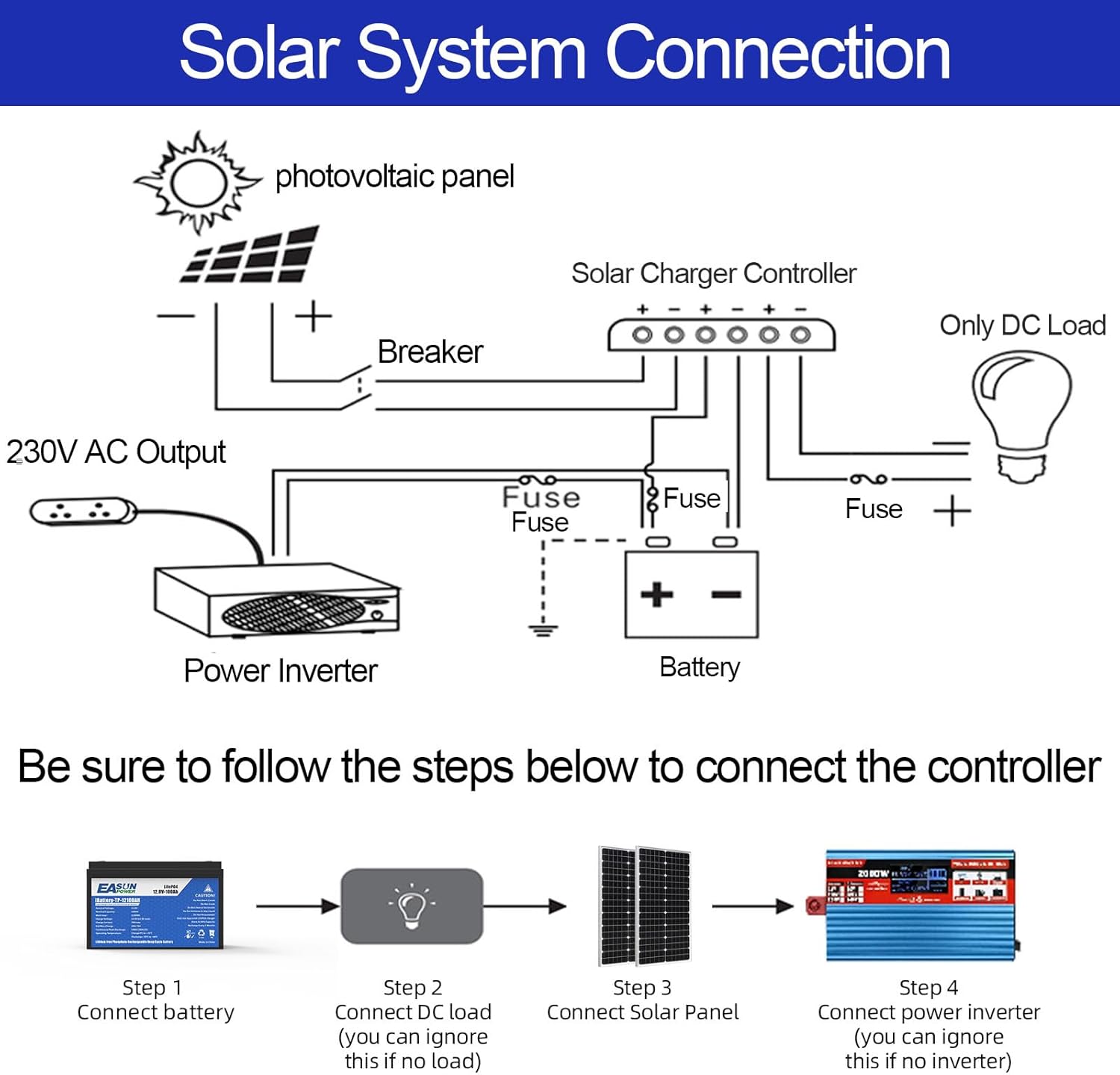
Figure 5: Solar System Connection Diagram
This diagram illustrates the typical connection sequence for a solar power system, showing the photovoltaic panel, breaker, solar charger controller, battery, power inverter, and optional DC load. It emphasizes connecting the battery first, then the DC load, then the solar panel, and finally the power inverter.

Figure 6: Solar System Connection with Power Values
This image provides a detailed connection diagram for a solar system, including solar panels, the MPPT charge controller, a battery, and an inverter connected to household appliances. A table below the diagram specifies battery voltage, objętość wejściowa PVtage range, and maximum PV input power for 20A, 30A, and 40A models.
5. Instrukcja obsługi
5.1 Wyświetlacz LCD i przyciski
The controller features an LCD display that shows various operational data and system status. Two buttons, "Menu" (Up arrow) and "Set" (Down arrow), are used for navigation and parameter adjustment.

Figure 7: Display and Buttons Overview
This image details the LCD display and button functions. It shows icons for PV array, battery, and load, indicating their status (Day/Night, Charging, Battery type, Load on/off). It also explains that the "Menu" button is for switching down and entering the next interface, while the "Set" button is for switching up and exiting without saving.
5.2 Menu Navigation and Parameter Settings
From the homepage, you can navigate through different display pages and enter settings mode.
- Short Press (Menu/Set): On the homepage, short press the "Menu" (Up) or "Set" (Down) button to switch between display pages (e.g., Homepage, Battery Temperature, Charging Current, Accumulated Discharging AH, Accumulated Charging AH, Discharging Current).
- Long Press (Menu): From the homepage, long press the "Menu" button for 3 seconds to enter the setting pages.
- Zmiana ustawień: Once in the setting pages, short press "Menu" or "Set" to switch between different setting parameters (e.g., System Battery, Battery Type, Low Voltage Recovery, Float Charging). To change a value, long press "Menu" until the item flashes, then use "Menu" or "Set" to adjust the value. Long press "Menu" again to save the changes.

Figure 8: Display Page Navigation
This image illustrates how to navigate through the controller's display pages by short-pressing the Menu or Set buttons. Pages shown include Homepage, Battery Temperature, Charging Current, Accumulated Discharging AH, Accumulated Charging AH, and Discharging Current.

Figure 9: Detailed Setting Pages
This diagram shows the various setting pages accessible by long-pressing the Menu button from the homepage. These include Resume Charging, Constant Voltage Charging (CV), Equalization Charging, Absorption Charging, Auto System Battery, Battery Type, Low Voltage Recovery, Low Voltage Protection, Float Charging, Temperature Compensation, Load Mode, and Communication Serial Number.

Figure 10: How to Change Settings (System Voltage Npample)
This image provides a step-by-step guide on how to change settings, using the battery system voltage jako example. It illustrates long-pressing "Menu" to enter settings, navigating to the System Voltage page, long-pressing "Menu" to make the item flash, using "Menu" or "Set" to change the value, and long-pressing "Menu" again to save.
5.3 Load Working Modes (for DC load only)
The controller offers four load working modes for managing connected DC loads. The default setting is 24-hour operation.
- Ld1: Regular Mode: The load operates continuously and can be manually turned on or off.
- Ld2: Light-controlled Mode: Obciążenie włącza się automatycznie o zmierzchu i wyłącza o świcie.
- Ld3: Light & Time-controlled Mode: Combines light control with a set timer. The load turns on at dusk and operates for a specified number of hours.
- Ld4: Reverse Light-controlled Mode: The load automatically turns off at dusk and turns on at dawn.
To switch the load On/Off from the homepage, short press the "Set" button.

Figure 11: Four Load Working Modes
This image describes the four available load working modes (Ld1: Regular Mode, Ld2: Light-controlled Mode, Ld3: Light & Time-controlled Mode, Ld4: Reverse Light-controlled Mode) for the DC load. It also shows how to toggle the load on/off from the homepage using the "Set" button.
6. Konserwacja
Regular maintenance ensures the longevity and optimal performance of your solar charge controller. Perform the following checks periodically:
- Kontrola wizualna: Check for any visible damage, loose connections, or corrosion on the terminals.
- Czystość: Utrzymuj kontroler w czystości, bez kurzu i zanieczyszczeń. Upewnij się, że otwory wentylacyjne nie są zablokowane.
- Integralność połączenia: Periodically check all wiring connections to ensure they are tight and secure.
- Stan baterii: Monitoruj pojemność bateriitage and performance. Ensure batteries are not overcharged or over-discharged.
- Warunki środowiskowe: Ensure the controller is operating within its specified temperature range and is protected from moisture.
7. Rozwiązywanie Problemów
This section provides guidance on common issues you might encounter with your solar charge controller. For more complex problems, please contact customer support.
| Problem | Możliwa przyczyna | Rozwiązanie |
|---|---|---|
| Kontroler się nie włącza / Brak wyświetlacza | Akumulator nie jest podłączony lub jego polaryzacja jest odwrotna; Pojemność akumulatoratage too low; Loose battery connection. | Ensure battery is connected correctly with proper polarity. Check battery voltage (musi być powyżej minimalnej objętości roboczej)tage). Tighten battery connections. |
| Bateria się nie ładuje | Solar panel not connected or reverse polarity; Insufficient sunlight; PV input voltage too low/high; Faulty solar panel. | Verify solar panel connections and polarity. Ensure adequate sunlight. Check PV input voltage is within specified range (16.8-60V for 12V system, 33.6-60V for 24V system). Test solar panel output. |
| Ładowanie nie działa | Load output disabled; Overload protection activated; Battery voltage too low; Loose load connection. | Check load working mode settings and ensure load output is enabled. Reduce load if overloaded. Charge battery. Tighten load connections. |
| Niewłaściwa pojemność akumulatoratage reading or parameter issues | Incorrect battery type setting; Software glitch; Sensor issue. | Verify the battery type setting matches your battery. Try restarting the controller by disconnecting all power sources (PV and battery) and reconnecting. If issues persist, contact support. |

Figure 12: Controller Protection Functions
This image highlights the various protection functions of the controller, including protection against reverse polarity of photovoltaic modules, reverse polarity of the battery, battery over-voltage, battery over-discharge, and overload.
8. Gwarancja i wsparcie
For warranty information, please refer to the documentation included with your purchase or visit the official POWLAND website. If you encounter any issues not covered in this manual or require further assistance, please contact POWLAND customer support through their official channels.
Producent: EASUN POWER
Data pierwszej dostępności: 15 Marzec 2024