1. Wprowadzenie
The ZOYI MD1 LCR Meter Smart Tweezers is a portable, handheld device designed for efficient measurement and identification of surface-mount device (SMD) components. It features automatic component identification, a wide measurement range for resistance, capacitance, and inductance, and a clear OLED display for presenting measurement results. This manual provides essential information for the safe and effective use of your MD1 LCR Meter.
2. Zawartość opakowania
Sprawdź, czy w przesyłce znajdują się wszystkie wymienione poniżej elementy:
- ZOYI MD1 LCR Meter Smart Tweezers
- Kabel ładujący USB-C
- Torba do przechowywania
- Extra Pair of Tweezers Clips (Tips)
- Instrukcja obsługi (ten dokument)
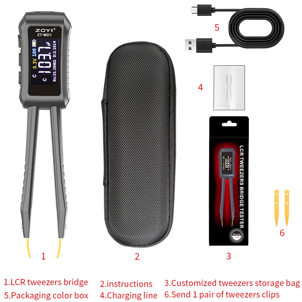
Figure 2.1: ZOYI MD1 LCR Meter and included accessories.
3. Setup and Overview
3.1 Ładowanie urządzenia
The ZOYI MD1 is powered by a built-in 400mAh lithium battery. To charge the device, connect the supplied USB-C cable to the charging port on the meter and to a standard USB power source (e.g., computer USB port, wall adapter). A full charge provides approximately 12 hours of continuous operation.
3.2 Koniec komponentuview
The device features an ergonomic design with an OLED display and replaceable test tips. The main body houses the display, control buttons, and internal circuitry, while the tweezer arms provide precise contact with components.

Figure 3.1: ZOYI MD1 LCR Meter Smart Tweezers.

Figure 3.2: Removable test tips and ergonomic design.
4. Instrukcja obsługi
4.1 Włączanie/wyłączanie zasilania
Press and hold the power button to turn the device on or off. The device features an automatic shutdown function to conserve battery life after a period of inactivity.
4.2 Automatyczna identyfikacja komponentów
The MD1 can automatically identify resistors, capacitors, inductors, and diodes upon contact. In 'AUTO' mode, simply clip the component with the tweezers, and the device will attempt to identify and measure it. This feature is designed to streamline the testing process for SMD components.
4.3 Manual Mode Selection
For specific component types or when auto-identification is not desired, you can manually select the measurement mode (L for Inductance, C for Capacitance, R for Resistance, Diode). Refer to the device's interface for button functions to cycle through modes.
4.4 Measurement Frequencies and Test Voltages
The device supports multiple test frequencies (100Hz, 1kHz, 10kHz) and test voltages (0.3V, 0.6V). These settings can be adjusted to suit different component types and measurement requirements, providing enhanced accuracy for various applications.
4.5 Interpreting the OLED Display
The vibrant OLED display shows primary and secondary measurement values simultaneously. The primary display area shows the main parameter (L, C, or R), while the secondary display area shows related parameters such as Rs (Series Resistance), Q (Quality Factor), or D (Dissipation Factor). The display also indicates the selected frequency, test voltage, and battery status.
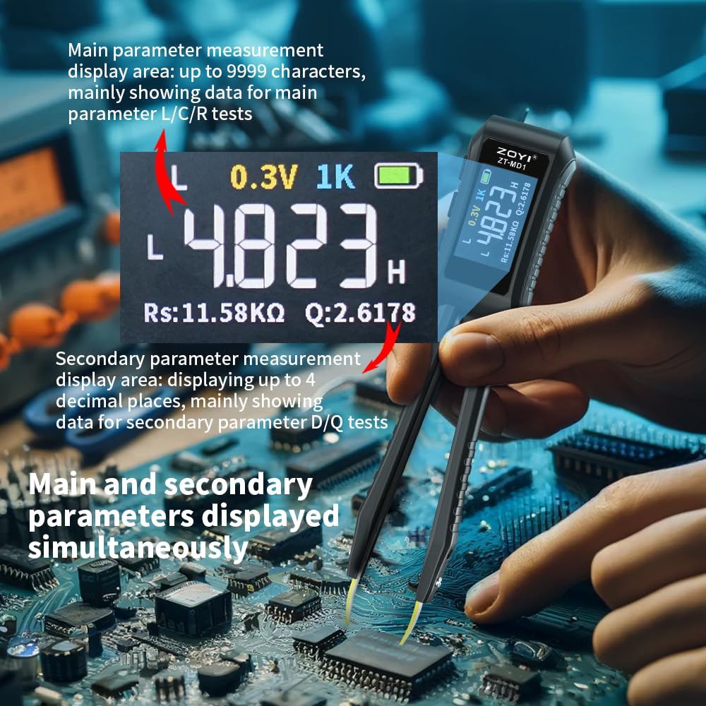
Figure 4.1: OLED Display showing main and secondary parameters.
4.6 Testing SMD Components
To test an SMD component, gently grasp it between the tweezer tips. Ensure good contact for accurate readings. The compact design allows for testing components directly on printed circuit boards (PCBs) or as loose components.
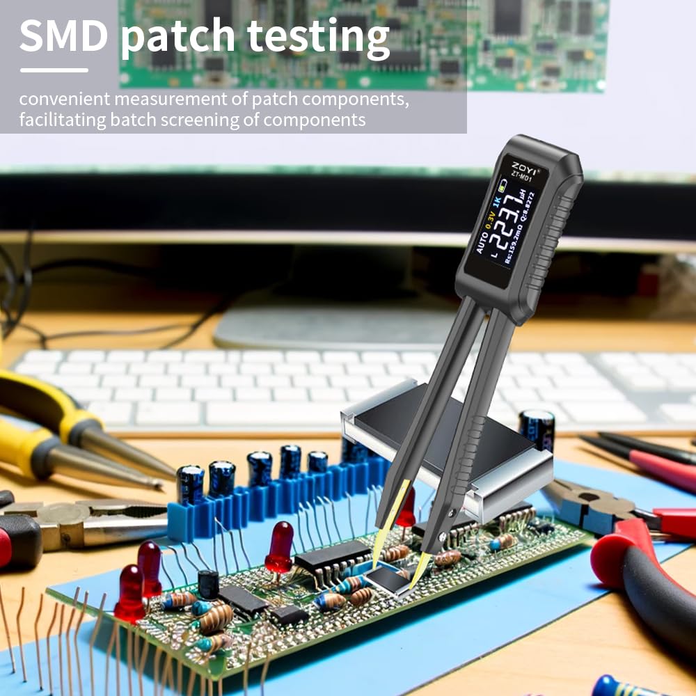
Figure 4.2: SMD patch testing in progress.
4.7 Zarządzanie danymi
The device automatically stores measurement results. You can connect the MD1 to a PC to export logs to Excel, facilitating project management and record-keeping.
5. Konserwacja
5.1 Czyszczenie
Regularly clean the device, especially the test tips, to ensure optimal performance. Use a soft, dry cloth. For stubborn residue on the tips, a small amount of isopropyl alcohol can be used, applied to a cotton swab, ensuring the device is powered off and disconnected from any power source.
5.2 Replacing Test Tips
The gold-plated test tips are replaceable. If the tips become worn or damaged, they can be exchanged for new ones. Refer to Figure 3.2 for the assembly of removable parts. Ensure the device is powered off before replacing tips.
5.3 Pielęgnacja baterii
To prolong battery life, avoid fully discharging the device frequently. Charge the device regularly, especially if it will be stored for an extended period.
5.4 Środki ostrożności
- Always ensure that the circuit or component being tested is de-energized and free of any residual charge before making contact with the MD1.
- For larger capacitors, it is recommended to discharge them fully before testing to prevent damage to the device.
- Do not use the device in wet conditions or in the presence of flammable gases or vapors.
6. Rozwiązywanie Problemów
- Inconsistent or Inaccurate Capacitance Readings:
Capacitance measurements can sometimes show variability. For critical measurements, consider taking multiple readings or using manual mode. Ensure good contact with the component and that it is fully discharged.
- Diodes Reported as BAD/OPEN:
The ZOYI MD1 has a maximum test voltage output of 0.6V. Many standard diodes (e.g., 1N4148, 1N400x series, and some LEDs) require a forward voltage greater than 0.6V to conduct. If a diode requires more than 0.6V to turn on, the MD1 may incorrectly report it as 'BAD' or 'OPEN'. This is a limitation of the device's design for certain diode types.
- Unreliable Auto-Identification:
While the auto-identification feature is convenient, it may not always accurately identify complex or unusual components. If you suspect an incorrect identification, switch to manual mode and select the expected component type (L, C, R, Diode) for a more precise measurement.
- No Reading or 'OL' (Overload) Displayed:
Ensure the component is properly gripped by the tweezers and that there is good electrical contact. Verify that the component's value falls within the MD1's specified measurement ranges. Check the battery level and recharge if necessary.
7. Specyfikacje
The following table details the technical specifications of the ZOYI MD1 LCR Meter:

Figure 7.1: ZOYI MD1 Technical Specifications.
| Funkcja | Szczegół |
|---|---|
| Numer modelu | MD1 |
| Wymiary produktu | 0.39 x 0.39 x 0.39 inches (approx. 146mm x 30mm) |
| Waga przedmiotu | 140 gramów (4.94 uncji) |
| Marka | ZOYI |
| Źródło zasilania | Zasilany bateryjnie (bateria litowa 400 mAh) |
| Wyświetlacz | Wyświetlacz OLED |
| Zakres oporu | 10mΩ - 10MΩ |
| Zakres pojemności | 1pF - 20mF (20,000µF) |
| Zakres indukcyjności | 1µH - 60H |
| Dokładność | Typically 0.5% (varies by range and frequency) |
| Częstotliwości testów | 100Hz, 1kHz, 10kHz |
| Objętość testowatages | 0.3V, 0.6V |
| Rejestrowanie danych | Auto-save, PC export via USB-C |
8. Wsparcie
For further assistance, technical support, or inquiries regarding your ZOYI MD1 LCR Meter, please refer to the official ZOYI website or contact their customer service department. Keep your purchase receipt for any warranty-related claims.