1. Wprowadzenie
This manual provides detailed instructions for the installation, operation, and maintenance of the SOBOUR FX3U-14MT/10MT High-Speed PLC Industrial Control Board. This programmable logic controller is designed for industrial automation applications, offering robust performance and compatibility with standard programming software.
Główne cechy:
- Supports ladder diagram programming language.
- Compatible with Mitsubishi GX-Developer and GX-WORK2 software.
- Enables human-machine interface (HMI) connection.
- Industrial-grade 32-bit MCU for strong anti-interference and high-speed operation.
- Integrated RS485 communication and clock functionality.
2. Koniec produktuview
The SOBOUR FX3U-14MT/10MT PLC board is a compact and powerful control unit. Familiarize yourself with the board's layout and components before proceeding with installation.
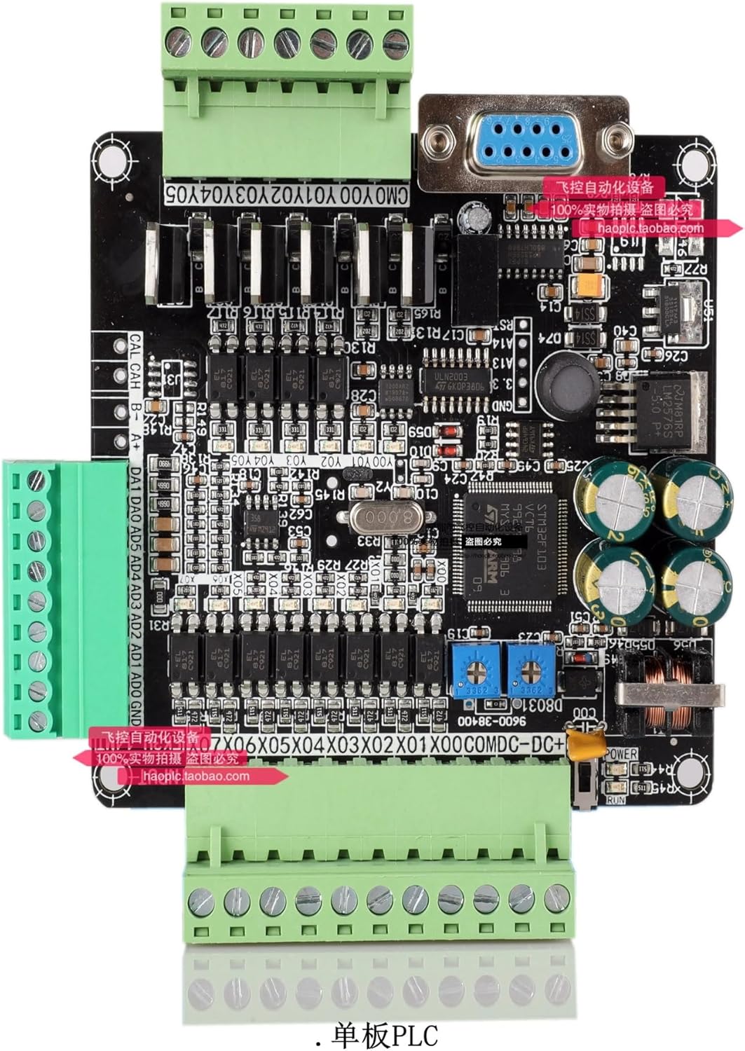
Figure 1: SOBOUR FX3U-14MT/10MT PLC Industrial Control Board. This image displays the bare board with green terminal blocks for input/output, a DB9 serial port, and various integrated circuits and capacitors. Key labels visible include CMO YOO Y01 Y02 Y03 Y04 Y05 (Digital Outputs), CAL CAH B- A+ (RS485 Communication), DA1 DA0 AD5 AD4 AD3 AD2 AD1 AD0 GND (Analog Inputs/Outputs), and X00 to X07 (Digital Inputs). The board also features a STM32F103 microcontroller, power regulation components, and status indicator LEDs.
Identyfikacja komponentu:
- Digital Inputs (X00-X07): Eight input terminals for connecting sensors and switches.
- Digital Outputs (Y00-Y05): Six output terminals for controlling actuators and relays.
- Analog Inputs (AD0-AD5): Six analog input channels.
- Analog Outputs (DA0-DA1): Two analog output channels.
- RS485 Communication (CAL, CAH, B-, A+): Terminals for RS485 serial communication.
- DB9 Serial Port: Standard serial port for programming and HMI connection.
- Power Input (DC+): Terminal for connecting the DC power supply.
- Microcontroller (STM32F103): The main processing unit of the PLC.
- Dioda LED zasilania: Wskazuje stan zasilania.
- Uruchom diodę: Indicates PLC operational status.
3. Konfiguracja i instalacja
Proper installation is crucial for the reliable operation of the PLC board. Follow these steps carefully.
3.1. Podłączenie zasilania
- Upewnij się, że napięcie zasilaniatage matches the PLC's requirements (typically 24V DC).
- Connect the positive (+) terminal of the power supply to the 'DC+' terminal on the board.
- Connect the negative (-) terminal of the power supply to the 'GND' terminal on the board.
- Przed podłączeniem zasilania sprawdź, czy wszystkie połączenia są pewne.
3.2. Okablowanie wejścia/wyjścia
Wire your sensors, switches, actuators, and other devices to the corresponding input (X) and output (Y) terminals. Refer to your application's wiring diagram for specific connections.
3.3. Programming Port Connection
Connect the DB9 serial port on the PLC board to your computer using a compatible programming cable. This port is used for program download, monitoring, and communication with HMI devices.
3.4. Instalacja oprogramowania
Install the necessary programming software, such as Mitsubishi GX-Developer or GX-WORK2, on your computer. Ensure the correct drivers for the programming cable are also installed.
4. Instrukcja obsługi
This section outlines the basic steps for operating your PLC board.
4.1. Programming the PLC
- Launch GX-Developer or GX-WORK2 software.
- Create a new project and select the appropriate PLC model (FX3U series).
- Write your application program using ladder diagram language.
- Connect the PLC to your computer via the programming port.
- Download the compiled program to the PLC.
4.2. Monitoring and Debugging
The programming software allows for real-time monitoring of PLC status, input/output states, and internal registers. Use these features to debug your program and verify correct operation.
4.3. Communication with HMI
The PLC supports communication with Human-Machine Interface (HMI) panels. Configure the HMI software to communicate with the PLC via the serial port, using the specified baud rate (38400 bps).
5. Konserwacja
Regular maintenance ensures the longevity and reliable performance of your PLC board.
5.1. Czyszczenie
Periodically clean the board to remove dust and debris. Use a soft, dry brush or compressed air. Ensure the power is disconnected before cleaning.
5.2. Zagadnienia środowiskowe
Operate the PLC in a clean, dry environment within its specified temperature and humidity ranges. Avoid exposure to excessive vibration, corrosive gases, or direct sunlight.
5.3. Aktualizacje oprogramowania sprzętowego
Sprawdź producenta website for any available firmware updates. Follow the provided instructions carefully when performing updates to ensure proper functionality.
6. Rozwiązywanie Problemów
W tej sekcji znajdziesz rozwiązania typowych problemów, na jakie możesz natrafić.
Typowe problemy i rozwiązania:
- PLC not powering on: Sprawdź połączenia zasilania i głośnośćtage. Check the Power LED.
- Program download failure: Ensure the programming cable is correctly connected, drivers are installed, and the correct COM port is selected in the software. Check PLC model selection.
- Inputs not responding: Check wiring of sensors/switches. Verify input status in monitoring software. Ensure input power supply is correct.
- Outputs not activating: Check wiring of actuators/relays. Verify output status in monitoring software. Ensure external power for outputs (if required) is connected.
- Communication errors with HMI: Verify serial port settings (baud rate, data bits, stop bits, parity) match between PLC and HMI. Check cable integrity.
7. Specyfikacje
| Funkcja | Opis |
|---|---|
| Model | FX3U-14MT/10MT |
| Mikrokontrolery | Industrial-grade 32-bit MCU (STM32F103) |
| Język programowania | Schemat drabinkowy |
| Zgodność oprogramowania | Mitsubishi GX-Developer, GX-WORK2 |
| Wejścia cyfrowe | 8 (X00-X07) |
| Wyjścia cyfrowe | 6 (Y00-Y05) |
| Wejścia analogowe | 6 (AD0-AD5) |
| Wyjścia analogowe | 2 (DA0-DA1) |
| Porty komunikacyjne | RS485, DB9 Serial Port |
| Szybkość transmisji | 38400 bps |
| Waga przedmiotu | 500 gramów (ok. 1.1 funtów) |
| UPC | 774284007498 |
8. Gwarancja i wsparcie
For warranty information and technical support, please refer to the SOBOUR official webOdwiedź witrynę lub skontaktuj się z autoryzowanym dealerem. Zachowaj paragon zakupu na wypadek reklamacji.