ETAxopowo B0CGNMRTJS
DIY Electronic Clock Kit Instruction Manual
Model: B0CGNMRTJS
1. Wprowadzenie
This instruction manual provides detailed guidance for assembling and operating the ETAxopowo DIY Electronic Clock Kit. Designed for adults and suitable for skill contests and training, this kit offers a hands-on learning experience in electronics and soldering. Please read all instructions carefully before beginning assembly.
2. Koniec produktuview
The DIY Electronic Clock Kit allows users to build a functional 6-bit digital circuit clock. The circuit is designed for accurate timekeeping using a quartz crystal oscillator and features a clear digital display.
Główne cechy:
- Dokładny pomiar czasu: Utilizes a quartz crystal as the time base pulse oscillator, ensuring precise time display through a counter, decoder, and display system.
- Seconds Signal Generator: Composed of CD4060 and CD4013 ICs, generating a 1 Hz time reference signal. The CD4060 acts as a 14-stage binary counter/frequency divider/oscillator, while the CD4013 provides an additional level of binary frequency division.
- Counter Circuitry: Seconds, minutes, and hours are managed by dual BCD synchronous plus counter CD4518 ICs, which output BCD code. The CD4511 IC decodes this BCD code for display. The seconds and minutes counters operate on a 60-decimal counting system, and the hours counter uses a 24-decimal counting system.
- Kalibracja czasu: Seconds can be calibrated using a waiting method via switch S3. Minutes and hours are adjusted by directly inputting pulse signals through dedicated switches.
- Wartość edukacyjna: This kit is widely used in educational settings to teach basic mechanical and electronic skills, circuit analysis, and soldering techniques.
Note: This circuit does not have a power failure memory function. Time will need to be recalibrated after a power interruption.

Figure 2.1: Fully assembled DIY Electronic Clock Kit, showcasing the digital display and circuit board.
3. Lista komponentów
Before starting assembly, ensure all components listed below are present in your kit. Refer to the circuit board diagram for component placement.
| Typ komponentu | Opis | Quantity (Approx.) |
|---|---|---|
| Płytka drukowana (PCB) | Main board for assembly | 1 |
| Digital Display Tubes | 7-segment LED displays (e.g., 5611AS) | 6 |
| Układy scalone (IC) | CD4060, CD4013, CD4518, CD4511, CD4581 | Różny |
| IC Sockets | For mounting ICs | Różny |
| Rezystory | Various values (e.g., 510Ω, 4.7KΩ, 100KΩ, 10MΩ) | Liczny |
| Kondensatory | Ceramic capacitors (e.g., 0.01µF, 22pF), Electrolytic capacitor (e.g., 100µF) | Różny |
| Diody | 1N4148 | Kilka |
| Oscylator kwarcowy | 32768Hz quartz crystal | 1 |
| Tact Switches | For setting time | 3 |
| Diody LED | Diody LED wskaźnikowe | Kilka |
| Terminal zasilania | For 5V power input | 1 |
| Kabel zasilający | Red and black wires | 1 zestaw |

Rysunek 3.1: Góra view of the circuit board, showing component placement and overall dimensions (130mm x 70mm).
4. Instrukcja montażu (konfiguracja)
Follow these steps carefully to assemble your DIY Electronic Clock Kit. Soldering experience is recommended. Always ensure proper component orientation and good solder joints.
4.1 Soldering Steps
Step 1: Solder Resistors and 1N4148 Diodes.
Begin by soldering all resistors onto the PCB. Pay attention to the resistance values as indicated on the board and component markings. Next, solder the 1N4148 diodes. Ensure the band on the diode matches the marking on the PCB for correct polarity.

Figure 4.1.1: Illustration of soldering resistors and 1N4148 diodes onto the circuit board.
Step 2: Solder Ceramic Capacitors and Crystal Oscillator.
Solder the ceramic capacitors (non-polarized) and the crystal oscillator onto their designated spots on the PCB. The crystal oscillator is typically a silver-colored component.

Figure 4.1.2: Illustration of soldering ceramic capacitors and the crystal oscillator.
Step 3: Solder IC Sockets, Tact Switches, and LEDs.
Solder the IC sockets onto the board. Ensure the notch on the socket aligns with the notch mark on the PCB. Then, solder the tact switches (push buttons) and the small indicator LEDs. For LEDs, observe polarity: the longer lead is typically positive (+).
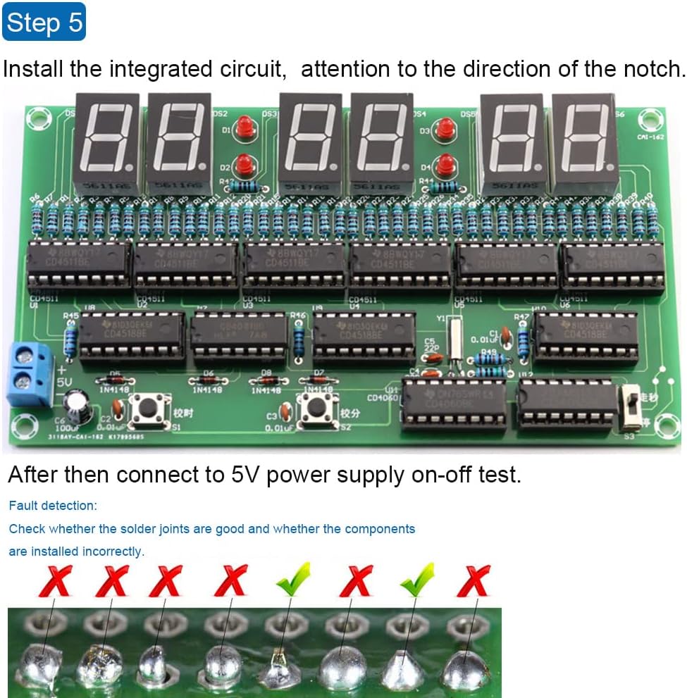
Figure 4.1.3: Illustration of soldering IC sockets, tact switches, and LEDs.
Step 4: Solder Digital Tubes, Electrolytic Capacitors, Toggle Switch, and Power Terminal.
Solder the digital display tubes (7-segment displays). Solder the electrolytic capacitors, ensuring the longer pin (positive) aligns with the '+' marking on the PCB. Solder the small toggle switch and the 5V power input terminal.
Figure 4.1.4: Illustration of soldering digital tubes, capacitors, toggle switch, and power terminal.
Step 5: Install Integrated Circuits (ICs).
Carefully insert the integrated circuits (CD4060, CD4013, CD4518, CD4511, CD4581) into their respective sockets. Ensure the notch on each IC aligns with the notch on the socket and the PCB marking. Apply gentle, even pressure to avoid bending pins.

Figure 4.1.5: Illustration of installing integrated circuits into their sockets, noting notch alignment.
4.2 Post-Assembly Check
After completing all soldering steps, perform a thorough visual inspection:
- Check all solder joints for proper connection, ensuring no cold joints or solder bridges.
- Verify that all components are installed in their correct positions and with the correct polarity (for diodes, LEDs, electrolytic capacitors, and ICs).
- Ensure no component leads are touching where they shouldn't, which could cause a short circuit.

Figure 4.2.1: Visual guide for identifying good and bad solder joints.
5. Instrukcja obsługi
Once assembled and powered, the clock will begin counting. Use the onboard switches to set the correct time.

Rysunek 5.1: Koniecview of the clock display and adjustment buttons.
5.1 Ustawianie czasu
- Adjusting Hours: Press the "Adjust Hour" tact switch (labeled S1) to increment the hour display.
- Adjusting Minutes: Press the "Adjust Minutes" tact switch (labeled S2) to increment the minute display.
- Calibrating Seconds: The seconds are calibrated using the toggle switch (labeled S3).
- In normal operation, ensure switch S3 is in the "go" position.
- To stop the seconds for calibration, move S3 to the "stop" position.
- When the standard time reaches the desired second, immediately switch S3 back to the "go" position to resume normal timekeeping.
Video 5.1.1: Demonstration of adjusting the hour and minute, and calibrating the seconds on the DIY Electronic Clock Kit.
Important: The clock does not retain time settings after power is removed. You will need to recalibrate the time after each power cycle.
6. Konserwacja
The DIY Electronic Clock Kit requires minimal maintenance once assembled. Follow these guidelines to ensure longevity:
- Czyszczenie: Use a soft, dry cloth to gently wipe the circuit board and display. Avoid using liquids or abrasive cleaners.
- Środowisko: Keep the clock in a dry environment, away from direct sunlight, extreme temperatures, and high humidity to prevent damage to electronic components.
- Obsługiwanie: Handle the assembled circuit board by its edges to avoid touching components or solder joints, which could cause damage or introduce static.
7. Rozwiązywanie Problemów
If you encounter issues with your DIY Electronic Clock Kit, refer to the following common problems and solutions:
| Problem | Możliwa przyczyna | Rozwiązanie |
|---|---|---|
| Clock does not power on or display anything. |
|
|
| Incorrect time display or erratic counting. |
|
|
| Individual segments or digits not lighting up. |
|
|
| Time resets after power off. | To jest oczekiwane zachowanie. | The kit does not include a battery backup or non-volatile memory for time retention. Time must be reset after each power cycle. |
8. Specyfikacje
- Wymiary produktu: 5.1 x 2.7 x 0.8 inches (130mm x 70mm x 20mm approx.)
- Waga przedmiotu: 2.08 uncji
- Producent: ETAxopowo
- Zalecany wiek: 16 lata i więcej
- Pobór mocy: 5V DC (via terminal)
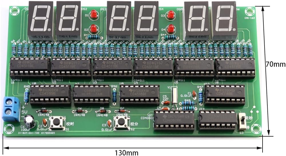
Figure 8.1: Dimensions of the assembled circuit board.
9. Gwarancja i wsparcie
For any questions regarding assembly, operation, or troubleshooting that are not covered in this manual, please contact the manufacturer or seller directly through the platform where the product was purchased. Please retain your proof of purchase for any warranty claims.
This product is intended for educational and hobbyist use. Proper handling and assembly are crucial for its functionality. The manufacturer is not responsible for issues arising from improper assembly or misuse.
Ask a question about this manual
Ask about setup, troubleshooting, compatibility, parts, safety, or missing instructions. Manuals+ will review the question and use this page’s manual context to help answer it.