1. Wprowadzenie
This user manual provides detailed instructions for the ZK-SMC02 DC Stepper Motor Controller Driver. This versatile module is designed to control 42/57 two-phase stepper motors, offering various control modes including automatic, manual, and serial communication. Please read this manual thoroughly before operation to ensure proper installation, safe use, and optimal performance of your device.
2. Funkcje produktu
- Supports automatic, manual, and serial communication control modes.
- Directly controls or cooperates with stepper motor drivers for 42/57 two-phase stepper motors.
- Compatible with most stepper motor drivers via pulse, direction, and enable interfaces.
- Features 9 operating modes with adjustable parameters, suitable for various applications.
- Allows saving and defining parameters such as distance, speed, delay, and cycle time, even after power-off.
- Can be used as a standalone unit or integrated into larger systems.
- Integrated acceleration and deceleration control.
- Input reverse connection protection.
3. Specyfikacje
| Parametr | Wartość |
|---|---|
| Odpowiedni silnik | 42/57 Two-phase Stepper Motor (Single Axis) |
| Control Axis Quantity | Pojedyncza oś |
| Sygnał silnika | Wspólna katoda |
| Zasilacz | DC 5-30V |
| Funkcja sterowania | Streamlined and optimized common instructions |
| Przyspieszenie/zwalnianie | Tak |
| Zabezpieczenie przed odwrotnym podłączeniem wejścia | Tak |
| Remote Communication Control | Port szeregowy TTL |
| Main System Function | Automatic / Manual / Setting / Serial Control |
| Zakres prędkości | 0.1-999 circles/minute |
| Forward Pulse Count | 1-9999 |
| Reverse Pulse Count | 1-9999 |
| Cycle Working Time | 1-9999 |
| Forward Delay Time | 0.0-999.9 sekund |
| Czas opóźnienia odwrotnego | 0.0-999.9 sekund |
| Subdivision Selection | 1-32 subdivision (for ZK-SMC02) |
| Zakres temperatur pracy | -5 ℃ ~ 60 ℃ (non-condensing) |
| Wymiary (dł. x szer. x wys.) | Approx. 79mm x 43mm x 41mm (including knob) |
4. Koniec produktuview i komponenty
4.1 Układ panelu przedniego
The front panel of the ZK-SMC02 features an LCD display, control buttons, and an encoder knob for easy operation and parameter adjustment.

Na tym zdjęciu widać górę view of the ZK-SMC02 controller. Key components include: CW (Clockwise) button for forward rotation, CCW (Counter-Clockwise) button for reverse rotation, a central LCD display, an encoder setting knob on the right, and a RUN/STOP button at the bottom right. Indicators for forward and reverse rotation are also visible above the display.
4.2 Komponenty wewnętrzne i połączenia
The internal board provides various connection terminals for power, motor, and serial communication.
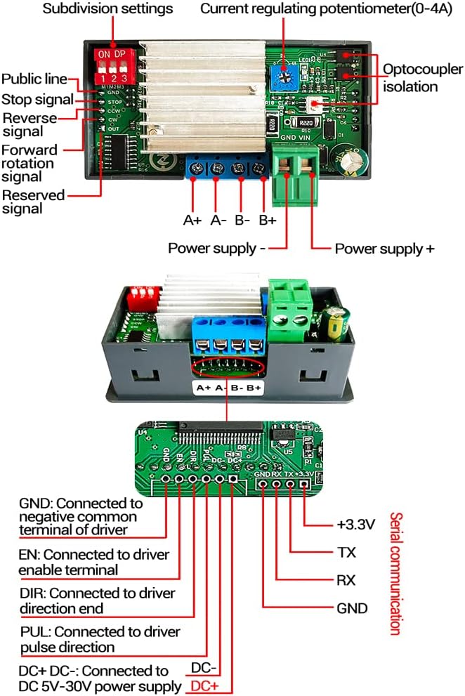
This image displays the internal circuit board of the ZK-SMC02. Visible components include subdivision settings DIP switches, a current regulating potentiometer, optocoupler isolation, and various connection terminals. These terminals are labeled for Public line, Stop signal, Reverse signal, Forward rotation signal, Reserved signal, Power supply (+/-), and motor connections (A+, A-, B+, B-). A separate section shows serial communication pins (GND, TX, RX, +3.3V) and driver connection pins (GND, EN, DIR, PUL, DC+ DC-).
4.3 Wymiary produktu
Understanding the physical dimensions is crucial for integration into your project.

This image provides two views of the ZK-SMC02 controller with its dimensions indicated in millimeters. The top view shows a length of 79mm and a width of 43mm. The side view shows a height of 26mm for the main body and 39mm including the knob, with a total depth of 71mm.
5. Konfiguracja i instalacja
Proper wiring is essential for the safe and correct operation of the ZK-SMC02 controller. Ensure all connections are secure before applying power.
5.1 Schemat okablowania
Follow the diagram below for connecting the stepper motor and power supply to the controller.

This image illustrates the wiring connections for the ZK-SMC02 controller. It shows a stepper motor connected to the controller's A+, A-, B+, B- terminals. A DC power supply is connected to the controller's power input terminals, with the positive (+) and negative (-) leads clearly marked. Ensure correct polarity when connecting the power supply.
5.2 Podłączenie zasilania
- Connect a DC power supply (5-30V) to the designated power input terminals on the controller. Observe polarity: connect positive to '+' and negative to '-'.
- Ensure the power supply can provide sufficient current for both the controller and the connected stepper motor.
5.3 Stepper Motor Connection
- Connect the stepper motor's coils to the A+, A-, B+, B- terminals on the controller as shown in the wiring diagram.
- Refer to your stepper motor's datasheet for correct coil identification if needed.
5.4 External Control (Optional)
- For external control via TTL serial communication or other signals (e.g., EN, DIR, PUL), refer to the internal component diagram (Figure 4.2) for pin assignments.
- Zapewnij odpowiednią objętośćtage levels and signal integrity for external connections.
6. Instrukcja obsługi
The ZK-SMC02 controller features a user-friendly interface for both running and setting parameters.
6.1 Koniec interfejsuview
The controller has two main interfaces: the Run Interface for real-time operation display and the Menu Setting Interface for parameter configuration.

This image shows two states of the ZK-SMC02's LCD display. The top display is the "RUN INTERFACE," which shows real-time operational information like "OUT" and a numerical value (e.g., 100.0, 2000). The bottom display is the "MENU SETTING INTERFACE," which shows parameter codes (e.g., F-01) and their values (e.g., 01), indicating where parameters can be modified.
6.2 Podstawowy schemat działania
The following steps outline how to navigate between the running interface and the menu settings, and how to adjust parameters.

This detailed image illustrates the operational flow of the ZK-SMC02. It shows how to exit the run interface and enter menu settings by long-pressing the encoder. Within the menu setting interface, the rotary encoder is used to change parameter codes (F-01 to F-13). Long-pressing the encoder saves parameters and returns to the running interface. For tuning individual parameters, short-pressing the encoder selects the parameter, which then flashes. Rotating the encoder adjusts the value, and another short press shifts to the next digit or confirms. Short-pressing the RUN/STOP button exits parameter setting and returns to the main menu number adjustment interface.
6.2.1 Run Interface Controls
- Przycisk CW: Initiates forward rotation.
- Przycisk CCW: Initiates reverse rotation.
- Enkoder obrotowy: Adjusts speed or other real-time parameters while in run mode.
- Przycisk URUCHOM/STOP: Stops the current operation and exits to the main menu.
6.2.2 Entering Menu Settings
- From the Run Interface, long press the Rotary Encoder to enter the Menu Setting Interface.
6.2.3 Navigating and Adjusting Parameters in Menu Settings
- In the Menu Setting Interface, rotate the Rotary Encoder to cycle through parameter codes (e.g., F-01 to F-13).
- To adjust a specific parameter (e.g., F-XX):
- Short press the Rotary Encoder to enter the parameter setting state. The parameter value will flash.
- Rotate the Rotary Encoder aby dostosować wartość.
- Short press the Rotary Encoder again to shift to the next digit or confirm the current digit.
- Once all digits are set, short press the RUN/STOP button to exit the parameter setting and return to the main menu number adjustment interface.
- To save parameters and exit the Menu Setting Interface: Long press the Rotary Encoder. This will save the current settings and return to the Run Interface.
7. Konserwacja
To ensure the longevity and reliable operation of your ZK-SMC02 controller, follow these general maintenance guidelines:
- Zachowaj czystosc: Regularnie czyść urządzenie miękką, suchą szmatką. Unikaj stosowania agresywnych środków chemicznych i materiałów ściernych.
- Środowisko: Operate the controller within its specified temperature and humidity ranges (-5 ℃ ~ 60 ℃, non-condensing). Avoid dusty, corrosive, or excessively humid environments.
- Znajomości: Periodically check all wiring connections to ensure they are secure and free from corrosion. Loose connections can lead to erratic behavior or damage.
- Wentylacja: Aby zapobiec przegrzaniu, należy zapewnić odpowiedni przepływ powietrza wokół kontrolera, zwłaszcza jeśli jest on zamknięty.
- Zasilanie: Use a stable and regulated DC power supply within the specified voltage range (5-30V). Fluctuations can damage the unit.
8. Rozwiązywanie Problemów
If you encounter issues with your ZK-SMC02 controller, refer to the following common problems and solutions:
| Problem | Możliwa przyczyna | Rozwiązanie |
|---|---|---|
| Kontroler nie włącza się. | Brak zasilania, nieprawidłowa głośnośćtage; odwrotna polaryzacja. | Sprawdź podłączenie zasilania i głośnośćtage (5-30V DC). Ensure correct polarity. |
| Silnik nie porusza się. | Incorrect motor wiring; motor disabled; parameters not set correctly; insufficient power. | Verify motor wiring (A+, A-, B+, B-). Check if motor is enabled (if using external enable). Review speed/pulse parameters. Ensure power supply can deliver enough current. |
| Motor moves erratically or vibrates. | Incorrect subdivision setting; loose motor connections; motor current too low/high. | Adjust subdivision settings. Secure all motor connections. Check motor driver current settings (if applicable). |
| Cannot enter menu settings. | Nieprawidłowy czas naciśnięcia przycisku. | Ensure you are long-pressing the Rotary Encoder from the Run Interface. |
| Parameters do not save. | Not exiting menu correctly. | Ensure you long-press the Rotary Encoder to save and exit the menu. |
Jeśli po wypróbowaniu tych rozwiązań problem nadal występuje, skontaktuj się z obsługą klienta, aby uzyskać dalszą pomoc.
9. Gwarancja i wsparcie
Ten produkt jest objęty standardową gwarancją producenta. Szczegółowe warunki gwarancji można znaleźć w dokumentacji dołączonej do produktu lub u sprzedawcy.
For technical support, troubleshooting assistance, or inquiries regarding product functionality, please contact the manufacturer or your authorized distributor. When contacting support, please provide your product model (ZK-SMC02) and a detailed description of the issue.
Manufacturer: Generic


