
Mars Gaming MCVIEW
Mars Gaming MC-VIEW Micro-ATX Gaming Mini Tower Case Instruction Manual
Model: MCVIEW
1. Wprowadzenie
This manual provides detailed instructions for the installation, operation, and maintenance of your Mars Gaming MC-VIEW Micro-ATX Gaming Mini Tower Case. Designed for custom PC configurations, the MC-VIEW offers a unique blend of compact size, aesthetic appeal, and high performance for gaming enthusiasts. Please read this manual thoroughly before beginning assembly to ensure proper setup and to maximize the lifespan of your components.

Figure 1.1: The Mars Gaming MC-VIEW Micro-ATX Gaming Mini Tower Case.
2. Główne cechy
- Continuous Frameless Tempered Glass Design: Showcases internal components with a 90-degree frameless tempered glass panel, offering an unobstructed view Twojej kompilacji.
- Modular Dual-Chamber Structure: Optimizes cooling and space by separating the power supply and storage drives into a hidden side compartment, ensuring efficient airflow and clean aesthetics.
- Expanded Micro-ATX Capacity: Compatible with Micro-ATX and Mini-ITX motherboards. Supports up to 7 fans, 5 storage drives, VGA cards up to 330mm in length and 148mm in width, and CPU coolers up to 158mm in height.
- Optimal Cooling and Liquid Cooling Support: Engineered for superior thermal performance, supporting liquid cooling systems with radiators up to 240mm at the rear and top.

Figure 2.1: Continuous frameless tempered glass design.

Figure 2.2: Expanded Micro-ATX capacity for various components.
3. Specyfikacje techniczne
| Atrybut | Szczegół |
|---|---|
| Marka | Mars Gaming |
| Nazwa modelu | MCVIEW |
| Zgodność płyty głównej | Micro ATX, Mini-ITX |
| Typ sprawy | Mini Tower |
| Kolor | Czarny |
| Tworzywo | Szkło hartowane, aluminium |
| Typ montażu zasilacza | Mocowanie dolne |
| Metoda chłodzenia | Powietrze, woda |
| Maksymalne wsparcie fanów | 7 (120mm/140mm) |
| Wsparcie chłodnicy | Up to 240mm (Rear, Top) |
| Maksymalna długość VGA | 330mm |
| Maksymalna szerokość VGA | 148mm |
| Maksymalna wysokość chłodnicy procesora | 158mm |
| Gniazda rozszerzeń | 4 |
| Wewnętrzne kieszenie na dyski | 5 (2.5-inch compatible) |
| Przednie porty we / wy | 2x USB 2.0, 1x USB 3.0, Audio Jack, Power Button, Reset Button |
| Waga przedmiotu | 3.95 kilograma |

Rysunek 3.1: Wymiary wewnętrzne i zgodność komponentów.
4. Konfiguracja i instalacja
Before starting, ensure you have all necessary components and tools. It is recommended to work on a clean, static-free surface.
4.1. Przygotowanie sprawy
- Rozpakuj obudowę: Carefully remove the MC-VIEW case from its packaging. Inspect for any damage.
- Zdejmij panele boczne: The tempered glass side panels are typically secured with thumbscrews or a latch mechanism. Remove them to access the interior.
- Zestaw akcesoriów: Locate the accessory kit, which usually contains screws, standoffs, and cable ties.
4.2. Instalacja płyty głównej
- Montaż elementów dystansowych: Ensure the correct standoffs are installed for your Micro-ATX or Mini-ITX motherboard. The case may have pre-installed standoffs.
- Zainstaluj osłonę I/O: Snap your motherboard's I/O shield into the rear opening of the case.
- Montaż płyty głównej: Carefully place your motherboard onto the standoffs, aligning the screw holes. Secure it with the provided screws.
4.3. Instalacja zasilacza (PSU)
The MC-VIEW features a dual-chamber design, with the PSU mounted in a separate compartment.
- Stanowisko PSU: Slide the PSU into its designated compartment at the bottom rear of the case. Ensure the fan faces the correct direction for optimal airflow (usually downwards or towards the side panel vent).
- Bezpieczny zasilacz: Fasten the PSU with screws from the rear of the case.
- Prowadzenie kabli: Route the necessary PSU cables through the cutouts into the main chamber for component connection.

Figure 4.1: Power Supply Unit (PSU) installation in the dedicated compartment.
4.4. Instalacja dysku pamięci masowej
The case supports up to 5 x 2.5-inch drives. Refer to the case's internal structure for specific mounting points, typically located in the secondary chamber.
- Locate Drive Bays: Identify the 2.5-inch drive mounting locations.
- Napędy montażowe: Secure your SSDs or HDDs using the provided screws.
- Podłącz kable: Attach SATA data and power cables to the installed drives.
4.5. Instalacja karty graficznej (VGA)
- Remove Expansion Slot Covers: Remove the necessary expansion slot covers at the rear of the case. Note that these are typically break-away covers and cannot be reattached.
- Insert VGA Card: Align your graphics card with the PCIe slot on the motherboard and press firmly until it clicks into place.
- Secure VGA Card: Przymocuj kartę graficzną do obudowy za pomocą śrub.
- Podłącz zasilanie: Attach any required PCIe power cables from the PSU to the graphics card.
4.6. Montaż układu chłodzenia (wentylatory i chłodnice)
The MC-VIEW supports up to 7 fans and liquid cooling radiators up to 240mm.
- Rozmieszczenie wentylatorów: Install fans in the designated locations (front, top, rear, bottom) using fan screws. Consider airflow direction (intake/exhaust).
- Umiejscowienie grzejnika: For liquid cooling, mount radiators (up to 240mm) at the top or rear of the case. Secure them with screws.
- Connect Fans/Pumps: Connect fan and pump cables to your motherboard or a fan controller.
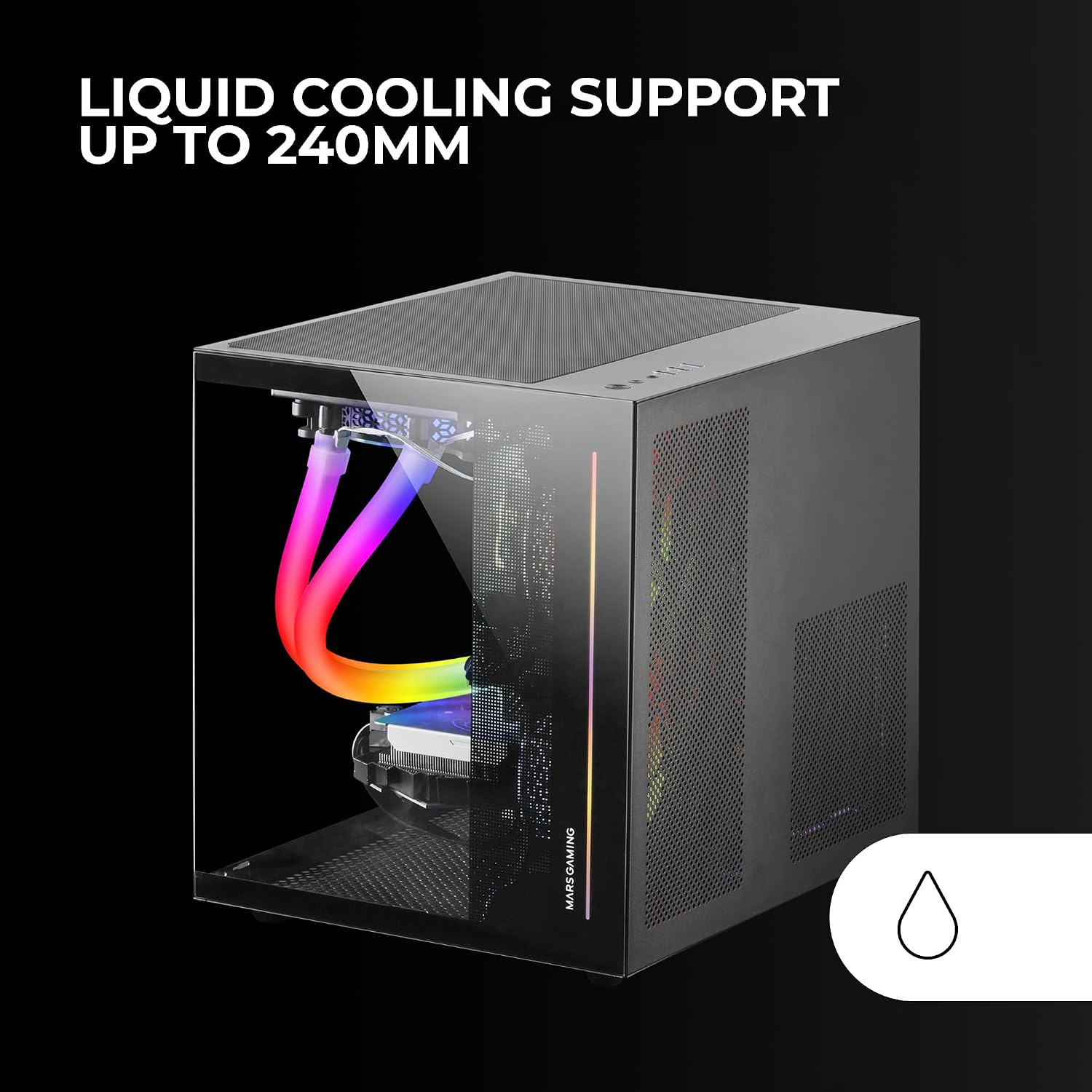
Figure 4.2: Liquid cooling system installed in the MC-VIEW sprawa.
4.7. Zarządzanie kablami
Utilize the dual-chamber design and cable routing cutouts to manage cables neatly. This improves airflow and aesthetics.
- Trasa kabli: Pass cables through the grommets and tie-down points behind the motherboard tray.
- Bezpieczne kable: Use cable ties (often included in the accessory kit) to bundle and secure cables.
- Connect Front Panel I/O: Connect the front panel USB, audio, power, and reset cables to the appropriate headers on your motherboard.

Figure 4.3: Modular dual-chamber structure for efficient cable management.
4.8. Montaż końcowy
- Reattach Panels: Once all components are installed and cables managed, carefully reattach the tempered glass side panels.
- Podłącz urządzenia peryferyjne: Podłącz monitor, klawiaturę, mysz i inne urządzenia peryferyjne do tylnych portów I/O.
5. Instrukcja obsługi
5.1. Włączanie/wyłączanie zasilania
- Włączanie: Press the power button located on the front I/O panel.
- Wyłączone: Initiate a shutdown from your operating system. For a forced shutdown, press and hold the power button for several seconds.
- Reset: Use the reset button on the front I/O panel for a system restart if needed.
5.2. Łączność na panelu przednim
Przedni panel I/O zapewnia wygodny dostęp do najważniejszych portów:
- Port USB 3.0 (x1): Do szybkiego przesyłu danych przy użyciu kompatybilnych urządzeń.
- Porty USB 2.0 (x2): Do podłączania standardowych urządzeń peryferyjnych USB.
- Wtyczka dźwiękowa: Do podłączenia słuchawek lub zestawu słuchawkowego.
6. Konserwacja
Regularna konserwacja pomaga zapewnić optymalną wydajność i długowieczność podzespołów komputera.
6.1. Zarządzanie pyłem
- Filtry przeciwpyłowe: The case includes a magnetic dust filter on the top panel. Regularly remove and clean this filter to prevent dust buildup.
- Czyszczenie wewnętrzne: Okresowo otwieraj obudowę i usuwaj kurz z wentylatorów, radiatorów i innych podzespołów za pomocą sprężonego powietrza. Przed czyszczeniem upewnij się, że system jest wyłączony i odłączony od zasilania.
6.2. Tempered Glass Care
- Czyszczenie: Use a soft, lint-free cloth and a mild glass cleaner (or water) to clean the tempered glass panels. Avoid abrasive materials or harsh chemicals.
- Obsługiwanie: Handle tempered glass panels carefully to prevent scratches or breakage.
7. Rozwiązywanie Problemów
W tej sekcji omówiono typowe problemy, na które możesz natrafić.
7.1. System się nie włącza
- Połączenia zasilania: Verify that the PSU is properly connected to the wall outlet and switched on. Check all internal power connections to the motherboard, CPU, GPU, and drives.
- Złącza panelu przedniego: Sprawdź, czy kabel przycisku zasilania na przednim panelu jest prawidłowo podłączony do złącza zasilania płyty głównej.
7.2. Problemy z przegrzewaniem
- Konfiguracja wentylatora: Check that all installed fans are operating and configured for optimal airflow (e.g., front/bottom intake, top/rear exhaust).
- Nagromadzenie kurzu: Clean any dust filters and internal components as described in the Maintenance section.
- Prześwit komponentów: Ensure no cables or other obstructions are blocking airflow to critical components.
7.3. Component Fitment Problems
- Sprawdź specyfikację: Refer to the Technical Specifications section for maximum supported dimensions for VGA cards, CPU coolers, and radiators.
- Przeszkoda kablowa: Ensure cables are not interfering with component installation.
- Expansion Slot Covers: Note that PCI expansion slot covers are break-away type. Once removed, they cannot be reattached. Plan accordingly before removing them.
8. Informacje o gwarancji
The Mars Gaming MC-VIEW case comes with a 3-letnia gwarancja producenta. This warranty covers defects in materials and workmanship under normal use. Please retain your proof of purchase for warranty claims. The warranty does not cover damage caused by improper installation, accidents, misuse, abuse, negligence, unauthorized modification, or natural disasters.
9. Wsparcie i kontakt
For further assistance, technical support, or to inquire about replacement parts, please visit the official Mars Gaming webna stronie internetowej lub skontaktuj się z działem obsługi klienta. Dodatkowe zasoby i informacje o produktach znajdziesz również na stronie Mars Gaming Store on Amazon.
10. Filmy produktowe
Brak konkretnego filmu URLs with creator type or preview information were provided in the product data. Please refer to the official Mars Gaming product page or support channels for any available instructional videos.
© 2024 Mars Gaming. Wszelkie prawa zastrzeżone.
Ask a question about this manual
Ask about setup, troubleshooting, compatibility, parts, safety, or missing instructions. Manuals+ will review the question and use this page’s manual context to help answer it.