1. Wprowadzenie
This manual provides detailed instructions for the installation, operation, and maintenance of the Supermicro X13SEI-F Server Motherboard. This motherboard is designed for high-performance server applications, supporting Intel Xeon processors with an LGA4677 socket and DDR5 memory.
Please read this manual thoroughly before attempting to install or operate the motherboard to ensure proper setup and to prevent damage to the components.
2. Informacje dotyczące bezpieczeństwa
Aby zapobiec obrażeniom ciała i uszkodzeniom sprzętu, należy przestrzegać następujących środków ostrożności:
- Always disconnect the power cord from the power supply before installing or removing any components.
- Podczas obsługi płyty głównej i innych podzespołów należy nosić opaskę antystatyczną na nadgarstku, aby zapobiec wyładowaniom elektrostatycznym (ESD).
- Ensure the installation environment is dry and free from static electricity.
- Nie wystawiaj płyty głównej na działanie wilgoci i ekstremalnych temperatur.
- Trzymaj płytę główną za krawędzie, aby uniknąć dotykania delikatnych podzespołów.
- Refer to the power supply unit's manual for specific safety guidelines related to power connections.
3. Zawartość opakowania
Verify that all items are present and in good condition. If any items are damaged or missing, contact your vendor.
- Supermicro X13SEI-F Server Motherboard
- Osłona We / Wy
- Kable SATA (ilość może się różnić)
- Quick Reference Guide / User Manual (this document)
- Płyta CD/DVD ze sterownikami lub napęd USB (lub instrukcja pobierania)
4. Koniec produktuview
The Supermicro X13SEI-F is a high-performance server motherboard featuring the LGA4677 socket, designed to support Intel Xeon Scalable processors. It offers robust memory capabilities with 8 DDR5 DIMM slots, supporting up to 4800MHz memory speed. The board also includes multiple PCIe slots for expansion.
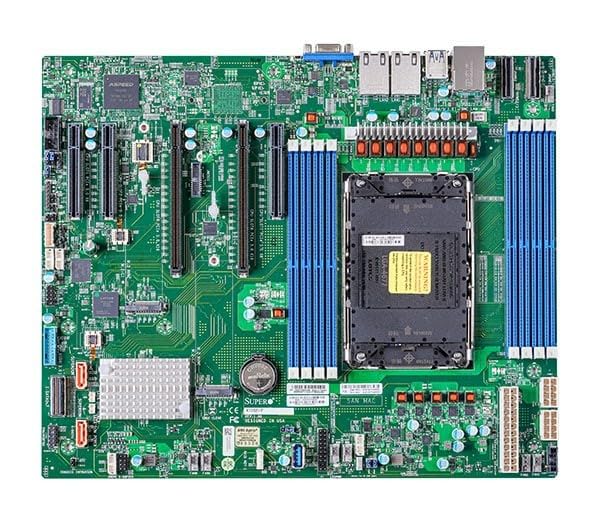
Figure 1: Supermicro X13SEI-F Server Motherboard. This image displays the overall layout of the motherboard, including the CPU socket, DIMM slots, and various connectors.
4.1 Główne cechy
- Gniazdo procesora: LGA4677 for Intel Xeon Scalable Processors
- Zestaw układów scalonych: Intel® C621
- Pamięć: 8x DDR5 DIMM slots, up to 4800MHz
- Gniazda rozszerzeń: Multiple PCIe slots (specific configuration depends on model variant)
- Składowanie: Support for various storage interfaces (SATA, NVMe - specific details in specifications)
- Sieciowanie: Integrated LAN controllers
5. Konfiguracja i instalacja
Before beginning installation, ensure your system case is compatible with the motherboard's form factor and that you have all necessary components.
5.1 Instalacja procesora (LGA4677)
- Znajdź gniazdo LGA4677 na płycie głównej.
- Carefully open the CPU socket retention mechanism according to the instructions provided with your CPU or motherboard.
- Align the CPU with the socket, ensuring the triangular mark on the CPU matches the mark on the socket. Do not force the CPU into the socket.
- Ostrożnie włóż procesor do gniazda.
- Close the CPU socket retention mechanism until it locks securely.
- Zainstaluj chłodzenie procesora zgodnie z instrukcją producenta.
5.2 Instalacja pamięci RAM (DDR5)
- Locate the 8 DDR5 DIMM slots on the motherboard.
- Otwórz zatrzaski mocujące na obu końcach gniazda DIMM.
- Dopasuj wycięcie na module pamięci DDR5 do wypustki w gnieździe DIMM.
- Insert the memory module firmly into the slot until the retention clips snap into place. Ensure both clips are closed.
- For optimal performance, refer to the motherboard's manual for recommended memory population order.
5.3 Instalacja karty PCIe
- Identify the appropriate PCIe slot for your expansion card (e.g., GPU, RAID card).
- Remove the corresponding expansion slot cover from your chassis.
- Align the PCIe card with the slot and press down firmly until it is fully seated.
- Secure the card with a screw or retention clip to the chassis.
5.4 Instalacja urządzenia pamięci masowej
- Dyski SATA: Connect SATA data cables from the motherboard's SATA ports to your SATA hard drives or SSDs. Connect power cables from the PSU to the drives.
- NVMe M.2 Drives: Locate the M.2 slots. Insert the M.2 drive at an angle, then push it down and secure it with the provided screw or retention mechanism.
5.5 Połączenia zasilania
- Podłącz 24-pinowe złącze zasilania ATX zasilacza do głównego gniazda zasilania na płycie głównej.
- Connect the 8-pin (or 4+4 pin) EPS 12V CPU power connector(s) to the corresponding sockets near the CPU.
- Sprawdź, czy wszystkie połączenia zasilania są bezpieczne.
5.6 Połączenia na panelu przednim
Connect the front panel cables (Power LED, HDD LED, Power Switch, Reset Switch, USB, Audio) from your chassis to the corresponding headers on the motherboard. Refer to the motherboard's silkscreen labels or the detailed manual for exact pin configurations.
6. Instrukcja obsługi
6.1 Pierwsze uruchomienie
- After completing all hardware installations, connect the monitor, keyboard, and mouse.
- Connect the power cord to the power supply and turn on the power switch on the PSU.
- Press the power button on your chassis.
- The system should power on, and you should see the BIOS/UEFI POST screen.
6.2 Konfiguracja BIOS/UEFI
Aby wejść do narzędzia konfiguracji BIOS/UEFI, naciśnij przycisk USUNĄĆ or F2 key repeatedly during the POST process. Within the BIOS/UEFI, you can configure:
- Kolejność rozruchu
- Czas i data systemowa
- Ustawienia procesora i pamięci
- Storage configurations (RAID, AHCI)
- Sterowanie prędkością wentylatora
- Ustawienia zabezpieczeń
Zapisz zmiany przed wyjściem z BIOS-u/UEFI.
6.3 Instalacja systemu operacyjnego
Insert your operating system installation media (USB drive or DVD) and set it as the primary boot device in the BIOS/UEFI. Follow the on-screen instructions to install your preferred operating system. After installation, install all necessary drivers from the Supermicro website or the provided driver media.
7. Konserwacja
7.1 Czyszczenie
- Regularly clean dust from the motherboard and system components using compressed air.
- Przed czyszczeniem należy upewnić się, że system jest wyłączony i odłączony od zasilania.
- Unikaj stosowania płynnych środków czyszczących bezpośrednio na podzespołach.
7.2 aktualizacji oprogramowania sprzętowego
Periodically check the Supermicro website for updated BIOS/UEFI firmware. Firmware updates can improve system stability, performance, and compatibility. Follow the specific instructions provided by Supermicro for updating the firmware to avoid system damage.
8. Rozwiązywanie Problemów
W tej sekcji znajdziesz rozwiązania typowych problemów, na jakie możesz natrafić.
8.1 Brak zasilania / Brak testu POST (autotest po włączeniu zasilania)
- Sprawdź połączenia zasilania: Ensure the 24-pin ATX and 8-pin EPS 12V power connectors are securely seated.
- Verify PSU: Test the power supply unit (PSU) with another system or a PSU tester.
- Ponowne osadzenie komponentów: Ponownie zamontuj procesor, moduły pamięci RAM i wszelkie karty rozszerzeń.
- Wyczyść pamięć CMOS: Refer to the motherboard manual for instructions on how to clear the CMOS (Complementary Metal-Oxide-Semiconductor) settings, which can resolve boot issues.
- Minimalna konfiguracja: Try booting with only the CPU, one RAM stick, and the necessary power connections.
8.2 Brak wyjścia wyświetlacza
- Połączenie monitora: Ensure the monitor is properly connected to the graphics output (either integrated or discrete GPU) and is powered on.
- Karta graficzna: If using a discrete graphics card, ensure it is fully seated in its PCIe slot and has all necessary power connectors from the PSU.
- Zintegrowana grafika: If your CPU supports integrated graphics, try connecting the monitor to the motherboard's video output to rule out a discrete GPU issue.
8.3 System operacyjny nie uruchamia się
- Kolejność rozruchu: Check the BIOS/UEFI settings to ensure the correct boot device (e.g., SSD, HDD) is selected as the primary boot option.
- Drive Connections: Verify that your storage drives are properly connected (data and power).
- Instalacja systemu operacyjnego: If the OS is newly installed, ensure the installation process completed successfully and all drivers are installed.
9. Specyfikacje
| Funkcja | Szczegół |
|---|---|
| Marka | Supermikro |
| Nazwa modelu | MBD-X13SEI-F-B |
| Gniazdo procesora | LGA 4677 |
| Kompatybilne procesory | Intel Xeon Scalable |
| Typ chipsetu | Intel® C621 |
| Technologia pamięci RAM | DDR5 |
| Prędkość pamięci | 4800MHz |
| Gniazda RAM | 8x DDR5 DIMM slots |
| Wymiary produktu (dł. x szer. x wys.) | 16 x 12 x 5 cala |
| Waga przedmiotu | 3.19 funta |
| Pierwsza dostępna data | 20 stycznia 2023 r. |
Note: Specifications are subject to change without notice. For the most current information, please refer to the official Supermicro product page.
10. Gwarancja i wsparcie techniczne
10.1 Informacje o gwarancji
Supermicro products are covered by a limited warranty. For detailed warranty terms and conditions, including duration and coverage, please visit the official Supermicro website or consult the warranty card included with your product. Keep your proof of purchase for warranty claims.
10.2 Wsparcie techniczne
For technical assistance, driver downloads, BIOS updates, and further product information, please visit the official Supermicro support webstrona:
https://www.supermicro.com/support
Before contacting support, please have your motherboard model number (MBD-X13SEI-F-B) and serial number ready.