BFT 2611893
Instrukcja obsługi napędu bramy skrzydłowej BFT Virgo SMART BT A20
Model: 2611893
Wstęp
The BFT Virgo SMART BT A20 electromechanical gate operators are designed for swing gates with a leaf weight up to 200 kg and a length up to 2 m. They are intended for installation on wide gate posts, with an installation dimension from the hinge axis to the post edge inside the property of up to 23.5 cm. These operators feature a 24V DC motor and an internal self-locking gearbox, meaning the mechanism locks after closing the gate, preventing manual opening. Electromechanical switches and mechanical limit stops built into the opening and closing drives allow for precise adjustment of the wing's end positions, eliminating the need for ground stops. This significantly reduces installation time. The frequency of use for these operators is up to 60 cycles per day.
Produkt ponadview
The BFT Virgo SMART BT A20 system includes several key components for automated gate operation.

Figure 1: Complete BFT Virgo SMART BT A20 gate opener kit, showing the two gate operators, three remote controls, two safety photocells, and a flashing warning light. Also included are mounting brackets and keys for manual release.
Główne cechy:
- Functional Thalia Light Control Unit with Display: Integrated control unit for easy programming and operation.
- Electromechanical Switch: Ensures precise control of gate movement.
- Amperometric Obstacle Detection: Enhances safety by detecting obstructions during gate operation.
- Personalized Key Release: Allows manual unlocking of the gate in case of power failure.
- Suitable for Wide Posts: Designed for versatile installation on various gate post types.
Specyfikacje

Figure 2: Detailed technical specifications of the BFT Virgo SMART BT A20 gate operator, highlighting key performance metrics and features.
| Specyfikacja | Wartość |
|---|---|
| Producent | BFT |
| Wymiary produktu | Wymiary 18.8 x 22.4 x 29.2 cm |
| Numer modelu | 2611893 |
| ASIN | B0BPSW42B2 |
| Objętość silnikatage | 24V prądu stałego |
| Max. Gate Leaf Weight | 200 kg na skrzydło |
| Max. Gate Leaf Length | 2 m na liść |
| Czas cyklu | 14 sekund |
| Częstotliwość użytkowania | Semi-intensive (up to 60 cycles/day) |
| Stopień ochrony | IP44 |
| Pobór mocy | 110 W |
Konfiguracja i instalacja
Proper installation is crucial for the safe and efficient operation of your BFT Virgo SMART BT A20 gate opener. It is recommended that installation be performed by qualified personnel.
Ogólne uwagi dotyczące instalacji:
- Ensure the gate structure is sound and moves freely without obstruction.
- Verify that the gate posts are strong enough to support the operator's weight and forces.
- Adhere to all local electrical codes and safety regulations.
- The system is designed for easy assembly and contains all necessary parts.

Figure 3: The BFT Virgo SMART BT A20 kit, emphasizing its ease of assembly and the integrated THALIA control unit.
Wymiary montażowe:
The operators are designed for installation on wide gate posts. The installation dimension from the hinge axis to the post edge inside the property can be up to 23.5 cm. Refer to the detailed diagrams for precise measurements.
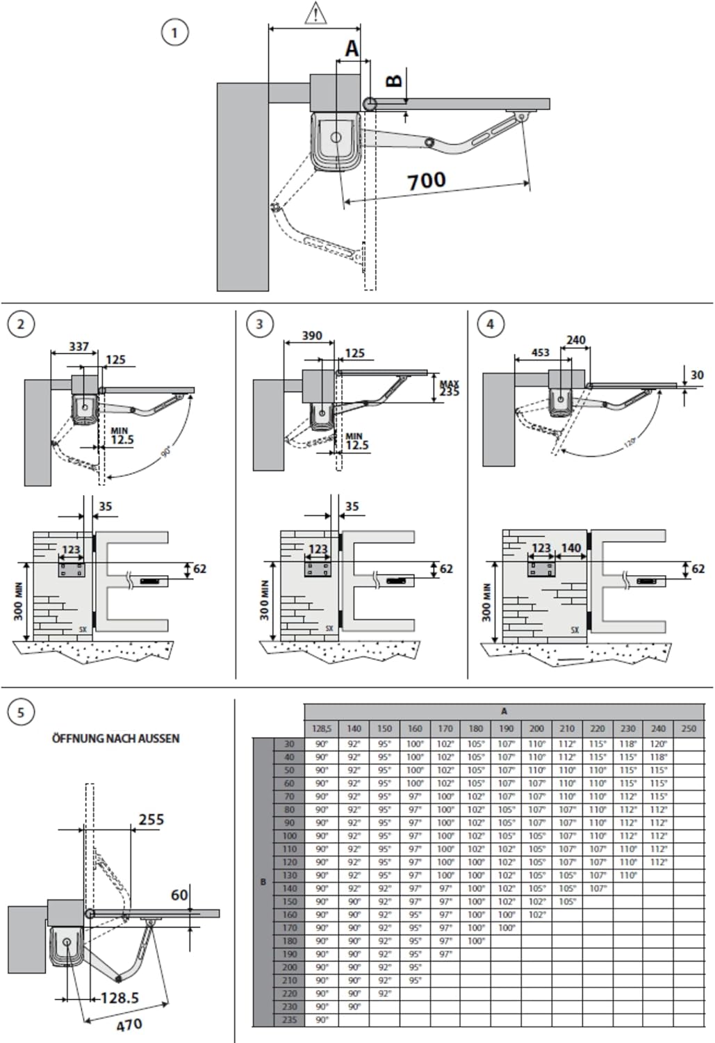
Figure 4: Installation diagrams illustrating various mounting configurations and critical dimensions for the gate operators, including details for inward and outward opening gates.
Instalacja komponentów:
- Gate Operators: Mount the operators securely to the gate posts and gate leaves using the provided brackets and hardware. Ensure correct alignment for smooth operation.
- Photocells (COMPACTA A20-180): Install the photocells at an appropriate height to detect obstacles. They offer adjustable heads for flexibility. Connect them to the control unit as per wiring diagrams.

Figure 5: BFT COMPACTA A20-180 photocells, designed for high installation flexibility with a 180-degree adjustable head and a 20-meter nominal range.
- Flashing Light (RADIUS LED): Mount the flashing light in a visible location to indicate gate movement. Connect it to the 24V power supply from the control unit.

Figure 6: BFT RADIUS LED flashing light, which includes an incorporated antenna and operates on a 24V power supply.
- Okablowanie: Connect all components to the Thalia Light control unit according to the provided wiring diagrams (not included in this manual, refer to the full installation guide). Ensure all electrical connections are secure and insulated.
- Wyłączniki krańcowe: The integrated electromechanical switches allow for precise adjustment of the gate's open and closed positions, eliminating the need for physical ground stops. Adjust these during the initial setup.
Instrukcja obsługi
Działanie pilota zdalnego sterowania:
The gate system is operated using the provided BFT Mitto 4-433 MHz rolling code remote controls.

Figure 7: BFT Mitto 4-433 MHz remote controller, detailing its features and dimensions.
- Press any button on the remote control to activate the gate.
- A single press will initiate the opening or closing cycle.
- Pressing the button again during operation will stop the gate.
- Trzecie naciśnięcie spowoduje zmianę kierunku działania bramy.
Zwolnienie ręczne:
W przypadku awarii zasilaniatage or malfunction, the gate can be manually opened using the personalized key.
- Locate the manual release mechanism on the gate operator.
- Insert the personalized key into the lock.
- Turn the key to disengage the motor, allowing the gate to be moved by hand.
- To re-engage, reverse the process and ensure the mechanism locks securely.
Konserwacja
Regularna konserwacja zapewnia długowieczność i niezawodną pracę napędu bramy.
- Miesięczny: Check the gate's mechanical components for any signs of wear, rust, or damage. Ensure the gate moves freely without the operator engaged.
- Kwartalny: Clean the photocell lenses to ensure proper obstacle detection. Inspect all electrical connections for corrosion or looseness.
- Rocznie: Have a qualified technician inspect the entire system, including motor, gearbox, and control unit, for optimal performance and safety.
- Keep the area around the gate and operators clear of debris.
Rozwiązywanie problemów
| Problem | Możliwa przyczyna | Rozwiązanie |
|---|---|---|
| Brama nie reaguje na pilota. | No power; remote control battery low; remote control out of range; photocells obstructed. | Check power supply; replace remote battery; move closer to gate; clear photocell path. |
| Gate stops or reverses during operation. | Obstacle detected by safety features (photocells, amperometric detection); gate mechanism obstructed. | Remove any obstacles; check gate path for physical obstructions. |
| Brama działa powoli lub z trudem. | Mechanical friction; low voltage; motor issue. | Lubricate hinges and moving parts; check power supply; contact service technician. |
| Flashing light does not illuminate. | Bulb/LED faulty; wiring issue; no power to light. | Check connections; replace light if necessary. |
Gwarancja i wsparcie
Informacje na temat gwarancji można znaleźć w dokumentacji dołączonej do zakupionego produktu lub uzyskać u sprzedawcy.
For technical support, spare parts, or professional assistance with installation and maintenance, please contact the authorized BFT service center or your product supplier.
Sprzedający: Automatyka.shop