
1. Wprowadzenie
This instruction manual provides detailed information for the proper setup, operation, and maintenance of the EC Buying SW-420 Vibration Sensor Module. This module is designed for detecting vibration and outputting a digital signal, making it suitable for various applications including alarm systems and microcontroller projects like those with Arduino.
The SW-420 is a normally closed type vibration sensor, meaning its output state changes upon detecting vibration. It features a wide voltage LM393 comparator for a clean output signal and robust driving capability.
2. Koniec produktuview
The EC Buying SW-420 Vibration Sensor Module is a compact and versatile component for detecting mechanical vibrations. It is supplied as a 5-piece package, ready for integration into your electronic projects.
- Utilizes a normally closed SW-420 vibration sensor.
- Incorporates a wide voltage LM393 comparator for stable digital output.
- Provides a clean digital switching output (0 and 1).
- Objętość operacyjnatagZakres: 3.3 V do 5 V.
- Equipped with bolt holes for easy mounting.
- Compact PCB size: 3.2 cm x 1.4 cm.
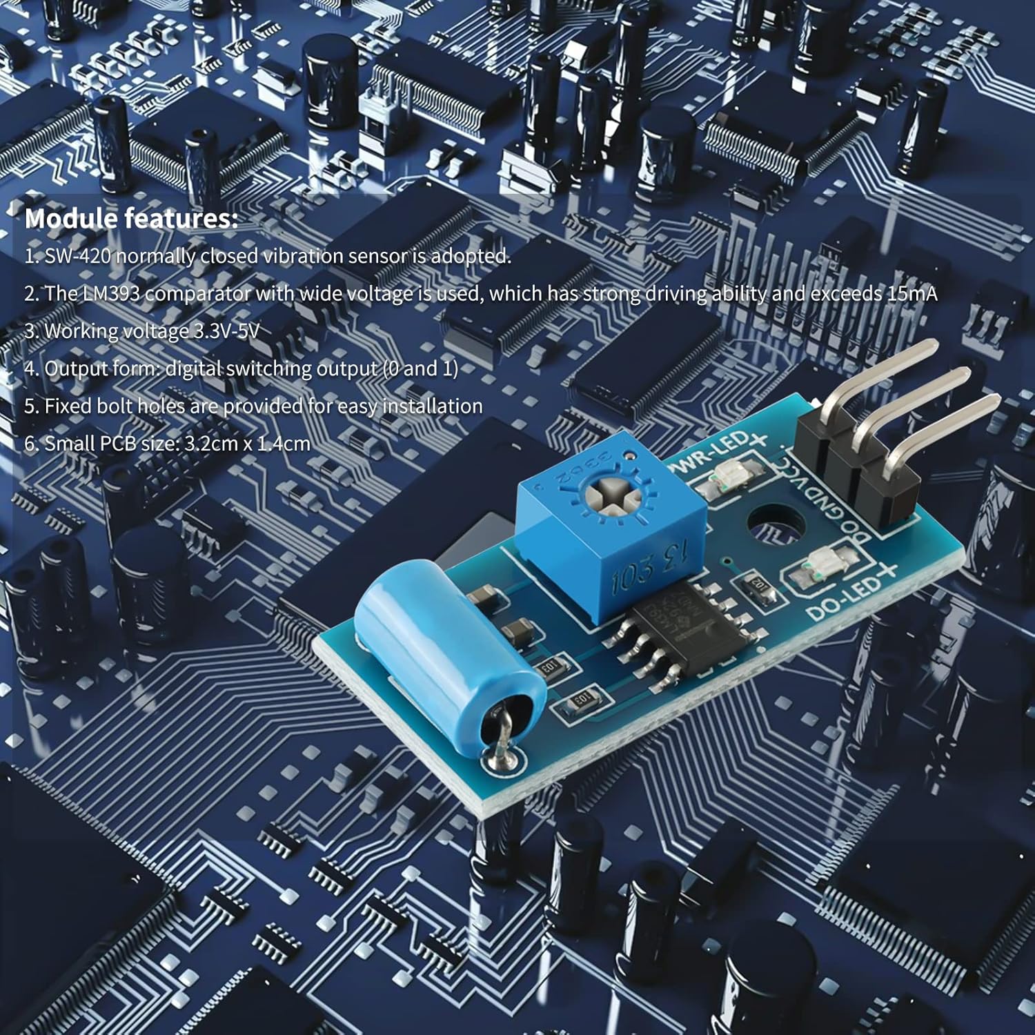
Figure 2.1: The SW-420 Vibration Sensor Module highlighting its key features and components.
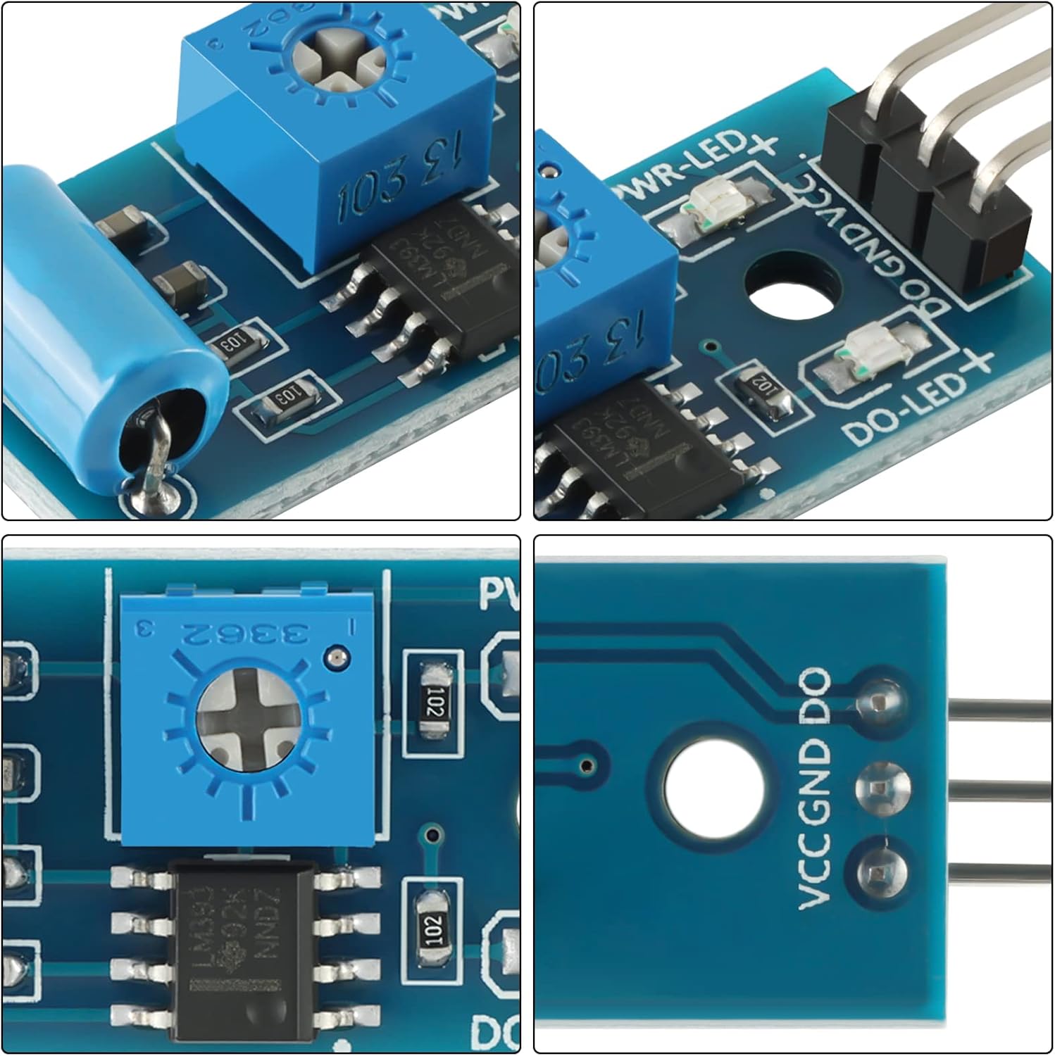
Rysunek 2.2: Szczegółowy views of the SW-420 module, showing the sensitivity adjustment potentiometer, the SW-420 sensor, and the output pins.
3. Konfiguracja i połączenie
This section details how to connect the SW-420 Vibration Sensor Module to a microcontroller, such as an Arduino. Ensure all connections are secure before applying power.
3.1 Opis wyprowadzeń
- VCC: Power supply positive (3.3V - 5V DC).
- masa: Grunt.
- DO (Digital Output): Digital switching output (0 or 1).
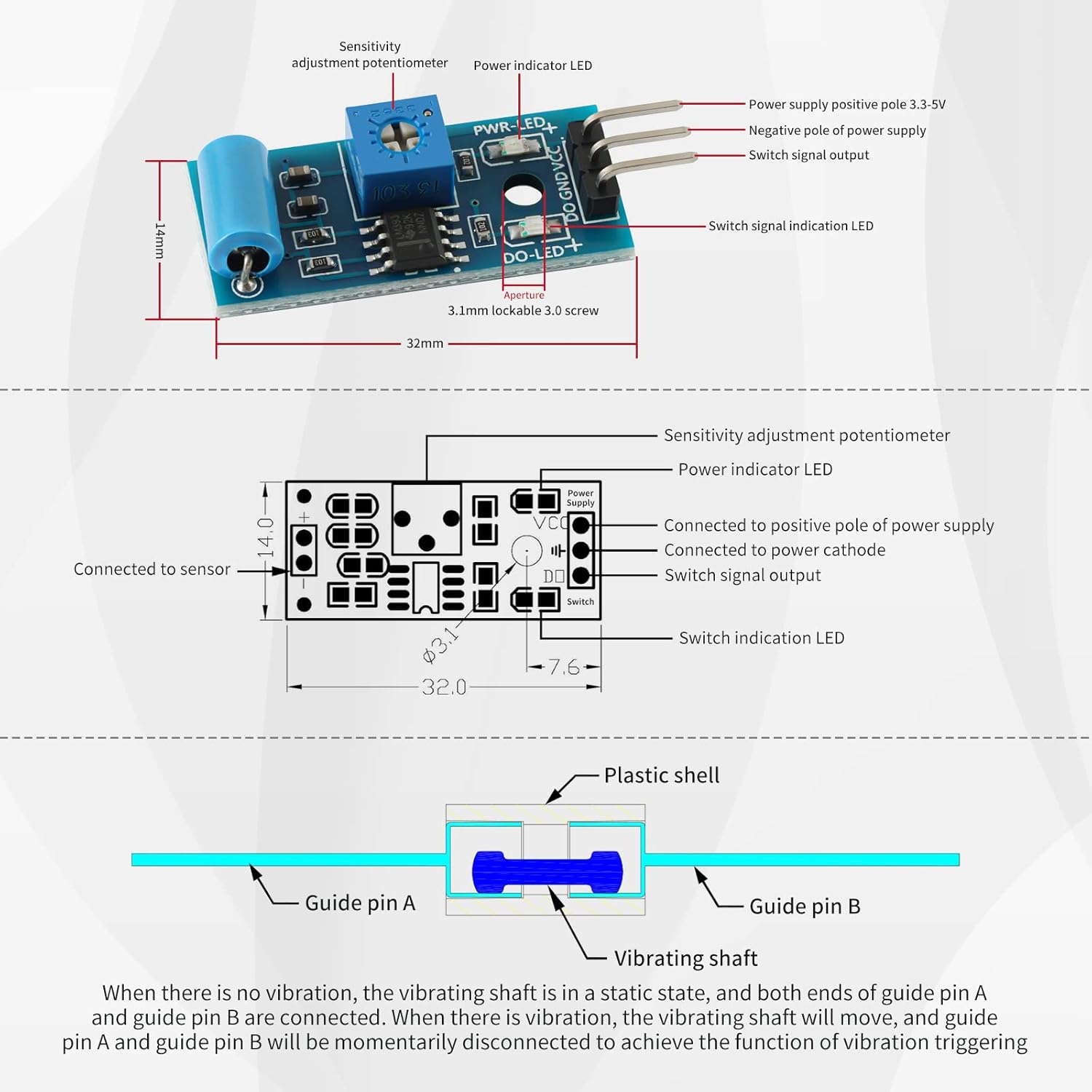
Figure 3.1: Pinout diagram and internal mechanism of the SW-420 module. The diagram illustrates the VCC, GND, and DO pins, along with the sensitivity adjustment potentiometer and LED indicators. The internal mechanism shows the vibrating shaft and guide pins.
3.2 Connecting to Arduino
Follow these steps to connect the SW-420 module to an Arduino board:
- Połącz VCC pin of the SW-420 module to the 5V pin on your Arduino board.
- Połącz GND pin of the SW-420 module to a GND pin on your Arduino board.
- Połącz DO (Wyjście cyfrowe) pin of the SW-420 module to a digital input pin on your Arduino (e.g., Digital Pin 2).
Ensure the power supply to the module is within the specified range of 3.3V to 5V.

Rysunek 3.2: Example wiring diagram for connecting the SW-420 Vibration Sensor Module to an Arduino UNO board. The module's VCC, GND, and DO pins are connected to the Arduino's 5V, GND, and a digital input pin, respectively.
4. Instrukcja obsługi
The SW-420 module operates as a normally closed vibration sensor. This means that in a static, non-vibrating state, the internal contacts (guide pins A and B) are connected. Upon detecting vibration, these contacts momentarily disconnect, triggering a change in the digital output signal.
4.1 Wyjście cyfrowe
The module provides a digital switching output (DO). When vibration is detected, the output state changes. It is important to monitor the zmiana in state rather than a continuous HIGH or LOW signal to accurately detect vibration events. For example, if the output is HIGH in a static state, it will momentarily go LOW upon vibration, and vice versa depending on the internal comparator configuration and sensitivity setting.
4.2 Regulacja czułości
The module includes a blue potentiometer (variable resistor) for adjusting sensitivity. Turning this potentiometer allows you to fine-tune the threshold at which the module detects vibration. Clockwise rotation typically increases sensitivity, while counter-clockwise rotation decreases it. Adjust this carefully to prevent false triggers or missed detections for your specific application.
4.3 Wskaźniki LED
The module features two LED indicators:
- Dioda PWR: Indicates that the module is receiving power.
- DO LED: Illuminates when the digital output (DO) changes state, indicating detected vibration.
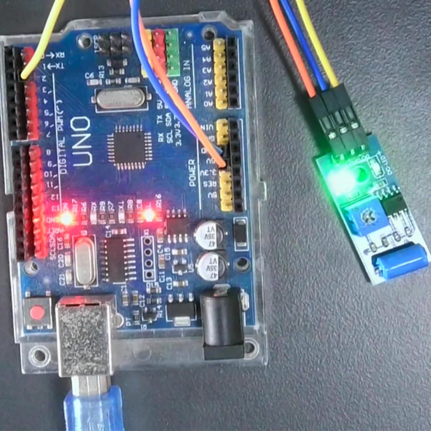
Figure 4.1: The SW-420 module in operation, connected to an Arduino. The illuminated LEDs indicate power and a detected vibration event.
5. Konserwacja
The SW-420 Vibration Sensor Module requires minimal maintenance. To ensure optimal performance and longevity:
- Utrzymuj moduł w czystości, bez kurzu i zanieczyszczeń. Do czyszczenia używaj miękkiej, suchej ściereczki.
- Unikaj wystawiania modułu na działanie nadmiernej wilgoci lub ekstremalnych temperatur.
- Handle the module with care to prevent physical damage to the sensor or PCB components.
- Regularly check connections for looseness or corrosion, especially in permanent installations.
6. Rozwiązywanie Problemów
If you encounter issues with your SW-420 Vibration Sensor Module, refer to the following troubleshooting tips:
6.1 No Output or Constant Output
- Sprawdź moc: Ensure the module is receiving stable power within the 3.3V-5V range. Verify the PWR LED is illuminated.
- Dostosuj czułość: The most common issue is incorrect sensitivity. Use a small screwdriver to slowly adjust the blue potentiometer. If the output is always HIGH or always LOW, try adjusting the potentiometer until the DO LED responds to light taps or vibrations.
- Sprawdź połączenia: Double-check all wiring to your microcontroller. Ensure VCC, GND, and DO pins are correctly connected.
6.2 False Triggers or Insufficient Sensitivity
- Dostosuj czułość: If the module is too sensitive (false triggers), turn the potentiometer counter-clockwise slightly. If it's not sensitive enough (missed detections), turn it clockwise. This may require trial and error.
- Orientacja montażu: Some users report that mounting the module with the pins facing downward can improve sensitivity. Experiment with different orientations if sensitivity is critical.
- Czynniki środowiskowe: Ensure the module is not exposed to unintended vibrations from its mounting surface or nearby equipment.
6.3 Incorrect Output Interpretation
- Remember that the SW-420 is a normally closed sensor. Its output indicates a zmiana in state due to vibration, not a continuous HIGH/LOW for vibrating/not vibrating. Your code should look for transitions (e.g., from HIGH to LOW or LOW to HIGH) to detect a vibration event.
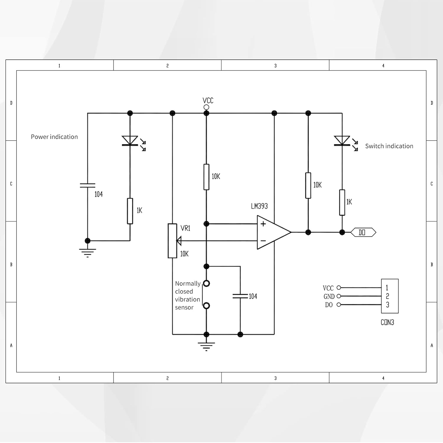
Figure 6.1: Schematic diagram of the SW-420 Vibration Sensor Module, showing the LM393 comparator, potentiometer (VR1), and the normally closed vibration sensor. This diagram can be useful for advanced troubleshooting.
7. Specyfikacje
| Funkcja | Specyfikacja |
|---|---|
| Model | SW-420 |
| Typ czujnika | Normally Closed Vibration Sensor |
| Komparator | LM393 Wide Voltage Komparator |
| Objętość operacyjnatage | 3.3 V - 5 V prądu stałego |
| Format wyjściowy | Digital Switching Output (0 and 1) |
| Driving Ability | >15mA |
| Wymiary płytki PCB (dł. x szer.) | 3.2 cm x 1.4 cm (32mm x 14mm) |
| Montowanie | Bolt holes for easy installation |
| Kompatybilne urządzenia | Arduino, Computers, Microcontrollers |
8. Gwarancja i wsparcie
For specific warranty information, please refer to the product packaging or contact your retailer. EC Buying is committed to providing quality electronic components.
For technical support or further inquiries, please visit the official EC Buying store or contact their customer service through the platform where the product was purchased.
Official EC Buying Store: EC Buying Store on Amazon