
1. Koniec produktuview
This document provides instructions for the aqxreight DC 12V-36V 15A 500W Brushless Motor Controller Hall BLDC Driver Board LJ. This board is designed for controlling brushless DC motors, offering stable operation and various control functions.

Rysunek 1: Ogólnie view of the aqxreight BLDC Driver Board.
Główne cechy:
- Szeroka objętość operacyjnatage: Supports DC 12V to 36V.
- Wysoka obciążalność prądowa: Operates with current up to 15A.
- Potężny sterownik: Capable of driving motors up to 500W.
- Kontrola prędkości: Adjustable speed via 0.1V-5V voltage wejście.
- Kontrola kierunku: Supports motor rotation direction change.
- Zintegrowane zabezpieczenia: Includes stall protection, overcurrent protection, and enable control.
- Hall Sensor Compatibility: Designed for brushless motors with Hall sensors.
2. Specyfikacje
| Parametr | Wartość |
|---|---|
| Objętość operacyjnatage | Prąd stały 12V-36V |
| Prąd roboczy | <= 15A |
| Moc sterownika | <= 500W |
| Prędkość Cztage | 0.1 V-5 V |
| Temperatura pracy | -40 do 85 °C |
| Wilgotność | 90% wilgotności względnej |
| Ochrona przed przeciągnięciem | Tak |
| Włącz kontrolę | Tak |
| Zabezpieczenie nadprądowe | Tak |
| Kontrola kierunku | Tak |
| Sygnał sterujący prędkością | Tak |
| Wymiary (dł. x szer. x wys.) | Wymiary: 63 x 42 x 17 mm |
| Mounting Hole Spacing (Length) | 57 mm |
| Mounting Hole Spacing (Width) | 36.5 mm |
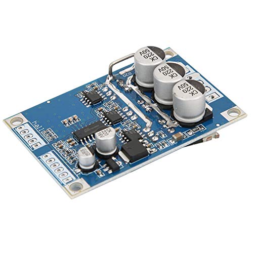
Figure 2: Dimensions of the BLDC Driver Board.
3. Konfiguracja i okablowanie
Proper wiring is crucial for the safe and correct operation of the BLDC driver board. Refer to the connection diagrams and descriptions below.
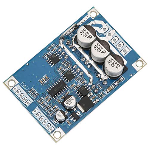
Rysunek 3: Góra view of the board with connection terminals.
3.1 Power Terminal Output
- VCC: Positive power supply input (DC 12V-36V).
- masa: Negative power supply input.
- MC (U): Motor phase U output.
- MB (V): Motor phase V output.
- MA (W): Motor phase W output.
3.2 Control Side Definition
- masa: Control terminal ground.
- Rzeczywistość wirtualna: Speed regulator input (0-5V). Corresponds to 10%-100% motor speed.
- ZF: Reverse control input. Connect to 5V or ground to change motor rotation direction.
- M: Tachometer pulse output. The number of pulses per revolution depends on the motor's pole count.
- EL: Enable control terminal. Connect to 5V to enable, ground to stop the motor.
- 5V: 5V control terminal output.
3.3 HALL Terminals
Connect the Hall sensor wires from your brushless motor to these terminals.
- 5V: Hall sensor positive power supply.
- Ha: Hall signal A input.
- Hb: Hall signal B input.
- Hc: Hall signal C input.
- masa: Hall sensor negative power supply.
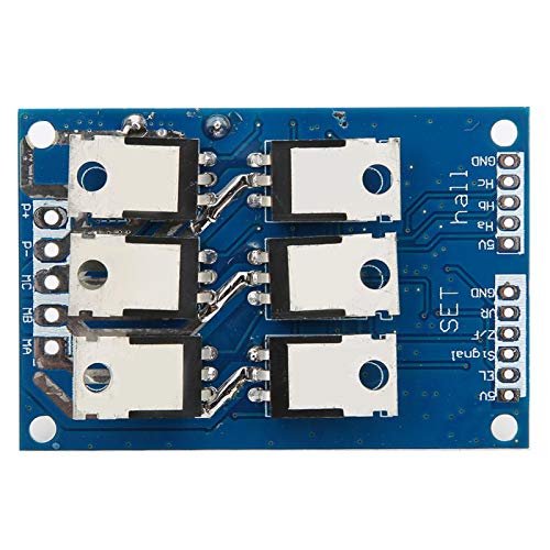
Rysunek 4: Dół view of the board, showing power components (MOSFETs).
4. Instrukcja obsługi
4.1 Włączanie/wyłączanie zasilania
- To power on the board, connect the DC 12V-36V power supply to the VCC and GND terminals.
- To enable the motor, ensure the EL (Enable) terminal is connected to 5V.
- To stop the motor, ground the EL terminal.
4.2 Kontrola prędkości
Motor speed is controlled by applying a voltage to the VR terminal:
- tomtage range of 0.1V to 5V on the VR terminal corresponds to 10% to 100% of the motor's maximum speed.
- Use a potentiometer or an external voltage source to provide the desired control voltage.
4.3 Sterowanie kierunkiem
The ZF terminal controls the motor's rotation direction:
- Connect the ZF terminal to 5V for one direction.
- Connect the ZF terminal to ground for the opposite direction.
5. Konserwacja
The aqxreight BLDC Driver Board is designed for durability. To ensure optimal performance and longevity:
- Utrzymuj deskę w czystości, bez kurzu i zanieczyszczeń.
- Avoid exposing the board to excessive moisture or extreme temperatures outside its specified operating range (-40 to 85 °C).
- Ensure proper ventilation to prevent overheating, especially during high-power operation.
- Regularly inspect connections for tightness and signs of corrosion.
6. Rozwiązywanie Problemów
If you encounter issues with your BLDC driver board, refer to the following common problems and solutions:
6.1 Motor Does Not Start or Operate
- Sprawdź zasilanie: Ensure the power supply is within the DC 12V-36V range and connected correctly (VCC and GND).
- Verify EL Terminal: Make sure the EL (Enable) terminal is connected to 5V to enable motor operation. If grounded, the motor will stop.
- Sprawdź połączenia silnika: Confirm that the motor phase wires (MC, MB, MA) and Hall sensor wires (Ha, Hb, Hc, 5V, GND) are securely connected and in the correct order. Incorrect Hall sensor wiring can prevent the motor from starting or cause erratic behavior.
- Check VR Input: Ensure the VR terminal is receiving a voltage between 0.1V and 5V. If VR is at 0V, the motor will not spin.
- Kompatybilność silnika: Verify that your motor is a brushless DC motor with Hall sensors and its power requirements (voltage, prąd, wattage) are within the board's specifications.
6.2 Motor Runs Erratic or at Incorrect Speed
- Hall Sensor Wiring: Recheck the Hall sensor connections. Incorrect phasing can lead to unstable operation.
- VR Signal Stability: Upewnij się, że objętośćtage signal to the VR terminal is stable and free from noise.
- Overcurrent/Stall Protection: If the motor is overloaded or stalled, the board's protection features may activate, causing intermittent operation or shutdown. Reduce load or clear obstructions.
6.3 Board Overheats
- Kontrola obciążenia: Ensure the motor's power consumption does not exceed 500W or 15A. Excessive load can cause overheating.
- Wentylacja: Provide adequate airflow around the board. Consider adding a heatsink or fan if operating at high power continuously.
- Zwarcia: Check for any accidental short circuits in the wiring, especially motor phases or power lines.
7. Gwarancja i wsparcie
This product has undergone testing before leaving the factory to ensure satisfactory performance. If you are not satisfied, the seller accepts requests for return, replacement, or refund as per their policy.
For further assistance or technical support, please contact the seller directly through the platform where the product was purchased. Please provide your order details and a clear description of the issue to facilitate a quicker resolution.
8. Oficjalne filmy o produktach
Nie znaleziono żadnych oficjalnych filmów produktu od sprzedawcy, które można by umieścić w tej instrukcji.