1. Wprowadzenie
This manual provides comprehensive instructions for the safe and effective use of your FavorCOOL AC Diagnostic Manifold Gauge Set. This multi-functional kit is designed for AC freon charging, evacuation, diagnostic checks, and recovery for both automotive and residential HVAC systems. It is compatible with R134A, R410a, R22, and R502 refrigerants.
Please read this manual thoroughly before operation to ensure proper usage and to prevent damage to the equipment or injury.
2. Koniec produktuview i komponenty
The FavorCOOL AC Diagnostic Manifold Gauge Set includes the following components:
- 3-Way Manifold Gauge with Sight Glass
- 3 Color-Coded Hoses (Red, Yellow, Blue)
- 2 Adjustable 1/4'' Snap-in Quick Couplers (High and Low Pressure)
- Brass Tank Adapter (R22 to R410a compatible)
- Can Tap Tool
- Portable Plastic Hard Case
2.1. Główne elementy
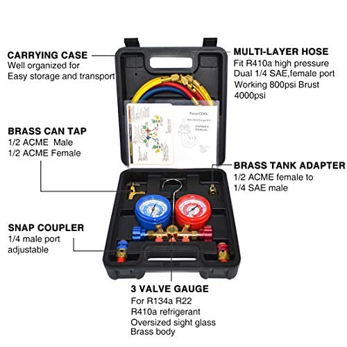
This image displays the organized layout of the manifold gauge set within its durable carrying case. Key components such as the multi-layer hoses, brass can tap, brass tank adapter, snap couplers, and the 3-valve gauge are clearly visible and labeled for easy identification and transport.
2.2. 3-Way Manifold Gauge

The manifold gauge features a blue low-pressure gauge (-30inHg to 550PSI) and a red high-pressure gauge (-30inHg to 760PSI). Both are color-coded for quick reference to pre-set scales for R22, R134a, and R410a refrigerants. A calibration screw allows for fine-tuning, and a transparent sight window enables monitoring of refrigerant quality and flow. The integrated hook provides convenient hanging during use.
2.3. High-Pressure Hoses
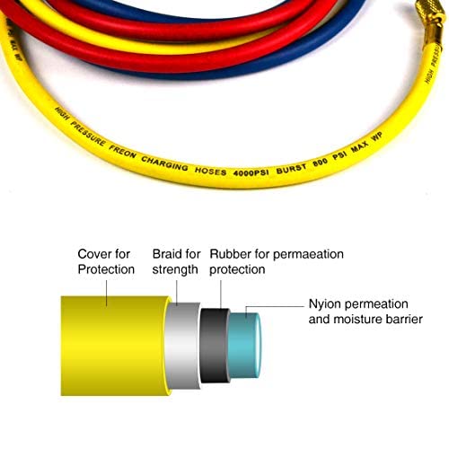
The kit includes three 4-foot color-coded hoses (red, yellow, blue) certified by CSA. These multi-layer hoses are constructed with 100% virgin Teflon diaphragms and other high-quality materials, offering anti-abrasion and anti-corrosion properties. They are rated for a working pressure of 800psi and a burst pressure of 4000psi, ensuring safety and durability during refrigerant charging, especially for R410a.
2.4. Adapters and Connectors
- Snap Quick Couplers: Designed for car R-134a service ports, with 1/4" SAE male connectors. Feature an integrated safety sleeve for secure connection.
- Can Tap Tool: Made of cast aluminum with 1/2" ACME male and female connectors.
- R22 to R410a Adapter: Solid brass adapter with 1/2" ACME female to 1/4" SAE male, allowing for versatile refrigerant compatibility.
3. Konfiguracja i połączenie
Before beginning any AC service, ensure you wear appropriate personal protective equipment, including safety goggles and gloves. Work in a well-ventilated area. Refer to the quick reference guide included with your kit for visual aid.
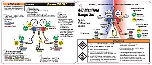
This guide provides a visual representation of the manifold gauge operation and hose connections for various AC service procedures.
3.1. Konfiguracja początkowa
- Unpack all components from the hard case.
- Inspect all hoses, gauges, and fittings for any signs of damage or wear.
- Ensure all valves on the manifold gauge are in the closed position (turned clockwise).
- If necessary, calibrate the gauges by adjusting the calibration screw to set the pointer to zero for precise readings.
3.2. Podłączanie węży
- Blue Hose (Low Pressure): Connect one end to the blue port on the manifold gauge. The other end connects to the low-pressure service port of the AC system (typically marked "L" or "Low").
- Red Hose (High Pressure): Connect one end to the red port on the manifold gauge. The other end connects to the high-pressure service port of the AC system (typically marked "H" or "High").
- Yellow Hose (Service/Charging): Connect one end to the central yellow port on the manifold gauge. The other end will connect to your vacuum pump, refrigerant tank, or can tap, depending on the operation.
For R-134a automotive systems, use the provided snap quick couplers on the blue and red hoses to connect to the vehicle's service ports. For other refrigerants or systems, use appropriate adapters as needed.
4. Instrukcja obsługi
Always consult the specific service manual for the AC system you are working on for precise pressure specifications and procedures. The following are general guidelines.
4.1. Pressure Reading
- Ensure all hoses are securely connected to the AC system and the manifold gauge.
- With the AC system running (if applicable for diagnostics), observe the pressure readings on both the blue (low-pressure) and red (high-pressure) gauges.
- Compare readings to the manufacturer's specifications for the specific refrigerant and ambient temperature.
4.2. Refrigerant Charging (General Procedure)
To jest uproszczoneview. Always follow industry best practices and safety protocols.
- Connect the yellow service hose to the refrigerant tank or can tap. Ensure the can tap is properly installed on the refrigerant can.
- Purge air from the yellow hose by slightly opening the manifold valve connected to the yellow hose for a brief moment, allowing a small amount of refrigerant to escape, then close it.
- Slowly open the low-pressure valve on the manifold gauge to allow refrigerant to flow into the AC system. Monitor the low-pressure gauge.
- For automotive systems, it is often recommended to charge through the low-pressure side with the engine running and AC on maximum.
- For residential systems, charging may involve both high and low sides, often with the system off or in specific modes.
- Close the manifold valve and the refrigerant tank/can tap once the desired charge is reached.
- Disconnect hoses carefully, being mindful of residual pressure.
4.3. System Evacuation (Vacuum)
Evacuation removes air and moisture from the AC system, which is critical for proper operation.
- Upewnij się, że wszystkie zawory rozdzielacza są zamknięte.
- Podłącz żółty wąż serwisowy do pompy próżniowej.
- Open both the high-pressure and low-pressure valves on the manifold gauge.
- Start the vacuum pump. The gauges should show a deep vacuum (below 0 PSI, into the negative pressure range).
- Allow the pump to run for a sufficient time (e.g., 30-60 minutes, or as specified by the system manufacturer) to ensure complete evacuation.
- Once evacuation is complete, close both manifold valves before turning off the vacuum pump.
- Obserwuj wskaźniki przez co najmniej 15–30 minut, aby upewnić się, że podciśnienie jest utrzymane i nie ma wycieków w układzie.
4.4. Video Demonstration: FavorCOOL AC Manifold Gauge Set Kit
This video provides a visual guide to the components and general usage of the manifold gauge set, complementing the written instructions.
5. Konserwacja
Proper maintenance ensures the longevity and accuracy of your manifold gauge set.
- Czyszczenie: After each use, wipe down the gauges, hoses, and fittings with a clean, dry cloth to remove any refrigerant residue or dirt. Avoid using harsh chemicals that could damage the components.
- Składowanie: Store the gauge set in its original hard case in a cool, dry place, away from direct sunlight and extreme temperatures. Ensure hoses are coiled neatly and not kinked.
- Kontrola: Regularly inspect hoses for cracks, cuts, or signs of wear. Check fittings for tightness and ensure O-rings are intact and not brittle. Replace worn components immediately.
- Kalibrowanie: Periodically check gauge calibration. If readings are consistently off, recalibrate using the adjustment screw or consult a professional.
6. Rozwiązywanie Problemów
W tej sekcji omówiono typowe problemy, na które możesz natrafić.
| Problem | Możliwa przyczyna | Rozwiązanie |
|---|---|---|
| Wskaźniki nie odczytują prawidłowo | Out of calibration, damaged gauge, air in lines. | Calibrate gauges, inspect for damage, purge lines. |
| Brak przepływu czynnika chłodniczego | Valves closed, clogged hose, empty tank. | Open valves, check hoses for kinks/blockages, verify tank content. |
| Odkurzacz nie trzyma | Leak in system or manifold set, loose connections. | Check all connections, inspect hoses and O-rings for leaks, use leak detection. |
| Quick couplers not connecting securely | Worn internal seals, debris, incorrect size. | Clean couplers, replace if worn, ensure correct coupler for service port. |
7. Specyfikacje
| Funkcja | Szczegół |
|---|---|
| Numer modelu | CT-536G-CP |
| Kompatybilne czynniki chłodnicze | R134A, R410a, R22, R502 |
| Low-Pressure Gauge Range | -30inHg to 550 PSI |
| High-Pressure Gauge Range | -30inHg to 760 PSI |
| Długość węża | 4 stóp (1.22 metry) |
| Ciśnienie robocze węża | 800 PSI |
| Ciśnienie pęknięcia węża | 4000 PSI |
| Tworzywo | Brass (manifold body, connectors) |
| Wymiary produktu | 10.79 x 9.8 x 3.82 cala (27.4 x 24.9 x 9.7 cm) |
| Waga przedmiotu | 4.54 funtów (2.06 kg) |
8. Gwarancja i wsparcie
Your FavorCOOL AC Diagnostic Manifold Gauge Set is covered by a 1-year limited manufacturer warranty. This warranty covers defects in materials and workmanship under normal use.
For technical assistance, warranty claims, or any questions regarding your product, please contact FavorCOOL customer support. Our USA-based team is available to provide professional service.
Informacje kontaktowe: Please refer to the contact details provided on the FavorCOOL official webAby uzyskać najbardziej aktualne informacje dotyczące pomocy technicznej, odwiedź witrynę lub opakowanie produktu.
Możesz również odwiedzić FavorCOOL Store on Amazon Aby uzyskać więcej informacji o produkcie i zasobach pomocy.