1. Wprowadzenie do produktu
The HYS TC-YG08 is a high-gain dual-band Yagi antenna designed for VHF (144MHz) and UHF (430MHz) frequencies. It features 8 elements to enhance transmission and reception capabilities for base or mobile radio transceivers. This manual provides detailed instructions for assembly, installation, and general use.
2. Zawartość opakowania
Przed rozpoczęciem montażu należy sprawdzić, czy w opakowaniu znajdują się wszystkie wymienione poniżej elementy:
- 1 x HYS YG08 Antenna (disassembled elements and boom sections)
- 1 x U-bolt Bracket Mount
- Screws and small parts for assembly
- 1 x Instrukcja obsługi (ten dokument)

Figure 2.1: All components included in the HYS TC-YG08 antenna package.
3. Instrukcja montażu
Follow these steps carefully to assemble your HYS TC-YG08 Yagi antenna. A screwdriver will be required for securing the elements.
Video 3.1: Step-by-step assembly guide for the HYS TC-YG08 Dual Band Yagi Antenna.
3.1. Assemble Elements 1-4 (VHF Section)
- Identify the main boom section with four pre-drilled holes on one side.
- Take element No. 1 and insert it into the corresponding hole on the boom. Secure it with a screw using a screwdriver.
- Repeat this process for elements No. 2, No. 3, and No. 4, ensuring each is firmly screwed into its designated hole.
3.2. Assemble Elements 5-6 (UHF Section)
- Locate the central feed point assembly, which typically has two shorter elements (No. 5 and No. 6) and a connector.
- Insert element No. 5 into its designated slot on the feed point assembly and secure it with a screw.
- Repeat for element No. 6.
3.3. Assemble Elements 7-8 (UHF Section)
- Identify the remaining boom section with two pre-drilled holes.
- Insert element No. 7 into its hole and secure with a screw.
- Repeat for element No. 8.
3.4. Connect Boom Sections
- Align the three assembled boom sections (VHF section, central feed point section, and UHF section).
- Carefully slide the sections together, ensuring the alignment pins (if present) match the corresponding holes.
- Secure the connections between the boom sections using the provided screws.

Figure 3.1: Assembled HYS TC-YG08 Yagi Antenna.
4. Instalacja
The HYS TC-YG08 antenna is designed for outdoor base station use. Proper installation is crucial for optimal performance and safety.
4.1. Miejsce montażu
- Choose a location free from obstructions (trees, buildings, power lines) that could interfere with signal transmission and reception.
- Mount the antenna as high as safely possible to maximize line-of-sight.
- Ensure the mounting surface or pole is sturdy enough to support the antenna, especially in windy conditions.
4.2. Attaching the Bracket
- Attach the U-bolt bracket mount to the main boom of the antenna.
- Secure the bracket to a mast or pole using the U-bolts and nuts, ensuring a tight and stable fit.
- The antenna can be mounted for either horizontal or vertical polarization, depending on your specific communication needs.
4.3. Połączenie kablem koncentrycznym
- Connect a high-quality 50 Ohm coaxial cable (not included) to the SO239 (UHF-Female) connector on the antenna's feed point.
- Ensure the connection is tight and weatherproof. Consider using self-amalgamating tape or silicone sealant to protect the connection from moisture.
- Route the coaxial cable away from metal objects and power lines to minimize interference.

Figure 4.1: Close-up of the SO239 (UHF-Female) connector on the antenna.
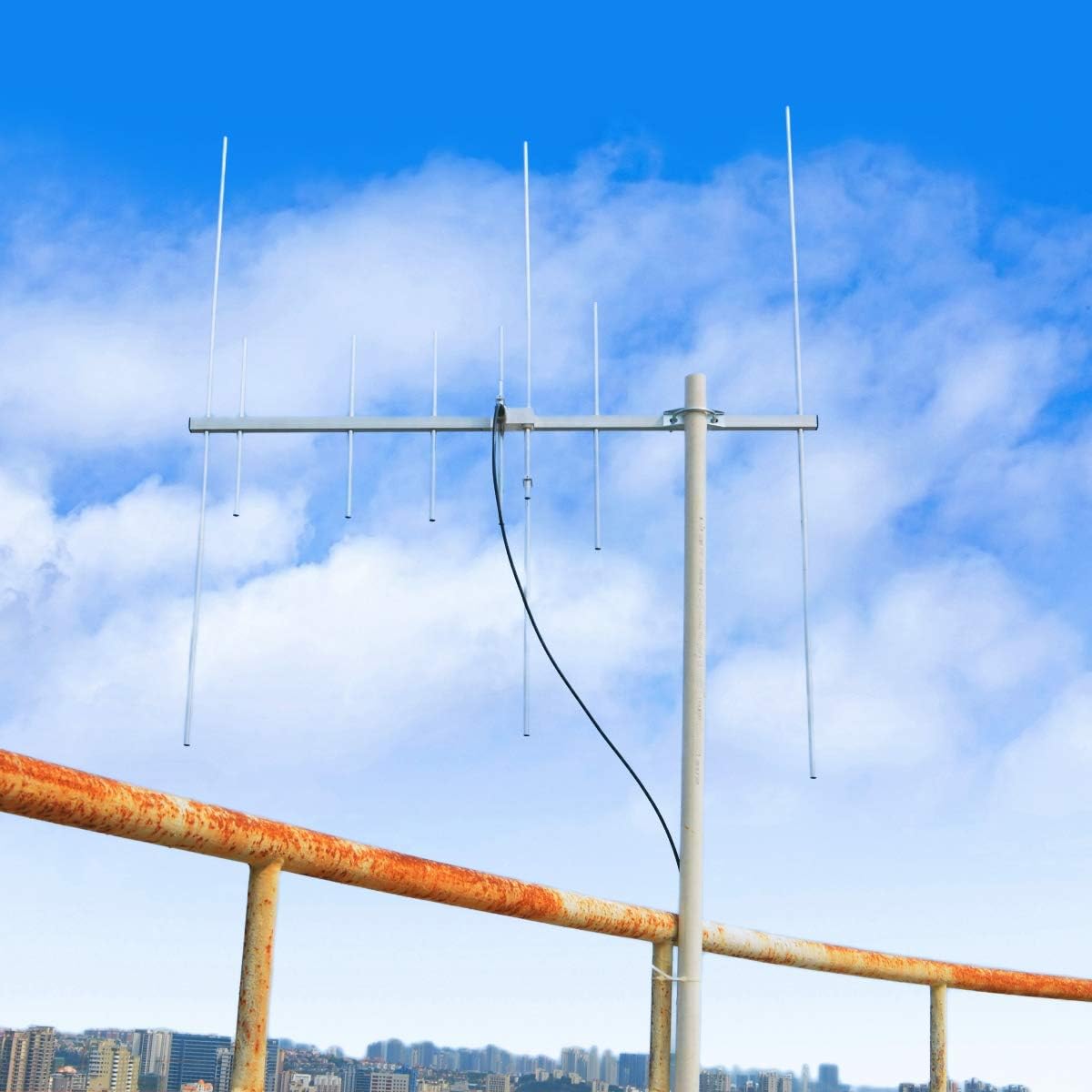
Rysunek 4.2: Example of outdoor antenna installation.
5. Instrukcja obsługi
Once the antenna is properly assembled and installed, connect it to your compatible mobile or base radio transceiver. Ensure your radio is set to the correct frequency band (VHF or UHF) and power output for your intended use. Always operate within legal power limits and frequency allocations.
6. Konserwacja
To ensure long-term performance and reliability of your HYS TC-YG08 antenna, consider the following maintenance tips:
- Regularna kontrola: Periodically check all connections, screws, and mounting hardware for tightness and corrosion.
- Czyszczenie: Clean the antenna elements and boom with a soft cloth and mild detergent if they become excessively dirty. Avoid abrasive cleaners.
- Ochrona przed warunkami atmosferycznymi: While designed for outdoor use, extreme weather conditions (heavy ice, strong winds) can cause damage. Inspect the antenna after severe weather events.
- Integralność kabla: Check the coaxial cable for any signs of wear, cracks, or damage, especially near connectors. Replace damaged cables promptly.
7. Rozwiązywanie Problemów
If you experience issues with your antenna, consider the following common troubleshooting steps:
- Poor Signal/High SWR:
- Check all physical connections for tightness and corrosion.
- Verify the coaxial cable is not damaged or kinked.
- Ensure the antenna elements are correctly assembled and secured according to the instructions.
- Confirm the antenna is oriented correctly for the desired signal path.
- Use an SWR meter to check the Standing Wave Ratio. High SWR can indicate a problem with the antenna, cable, or connection.
- Działanie przerywane:
- Inspect for loose connections at both the antenna and the radio.
- Check for water ingress into connectors or cable.
- Brak odbioru/transmisji:
- Ensure the radio is powered on and functioning correctly with another antenna (if available).
- Verify the coaxial cable is properly connected and not broken.
8. Specyfikacje
| Funkcja | Specyfikacja |
|---|---|
| Model | TC-YG08 |
| Zakres częstotliwości | 136-174MHz (VHF) & 400-470MHz (UHF) |
| Impedancja | 50 omy |
| Współczynnik SWR | <1.5 |
| Osiągać | 9.5dBi (VHF) / 11.5dBi (UHF) |
| Polaryzacja | Pozioma lub pionowa |
| Złącze | SO239 (UHF-Female) |
| Maksymalna moc wejściowa | 100 W |
| Wymiary | 925 × 1045 × 60 mm |
| Liczba elementów | 8 |
9. Obsługa klienta i gwarancja
For any questions, missing accessories, or support needs regarding your HYS TC-YG08 Dual Band Yagi Antenna, please contact the seller directly. They are committed to assisting you with any issues you may encounter.
Specific warranty details may vary; please refer to your purchase documentation or contact the seller for more information.