1. Wprowadzenie
The Acegmet JXM8000 is a True RMS (TRMS) digital multimeter designed for accurate and reliable electrical measurements. It features both automatic and manual ranging capabilities, allowing for versatile use in various applications. This manual provides essential information for the safe and effective operation, maintenance, and troubleshooting of your device.
2. Informacje dotyczące bezpieczeństwa
Always adhere to safety precautions when using electrical testing equipment. Failure to do so may result in electric shock, injury, or damage to the multimeter or equipment under test.
- Zabezpieczenie przed przeciążeniem: The multimeter is equipped with overload protection. When the input voltage is below 250V, the device automatically prevents burnout.
- Fuse Disconnect Function: In case of excessive current, the internal fuses will blow to protect the multimeter's internal circuitry. If a fuse blows, the screen will display "FUSE" and an alarm will sound.
- Wrong Polarity Alarm: If the test leads are connected to ports that do not match the selected measurement function (gear position), the screen will display "LEAD" and emit an audible beep. Correct the lead connection immediately.
- Ensure the multimeter's safety class (IEC61010 CAT.600V CAT IV, 1000V CAT.III) is appropriate for the measurement task.
- Nie próbuj mierzyć objtagprądów lub natężeń przekraczających określone maksymalne limity.
- Przed każdym użyciem sprawdź przewody pomiarowe pod kątem uszkodzeń. Uszkodzone przewody należy natychmiast wymienić.
- Nie używaj multimetru, jeśli wydaje się uszkodzony lub nie działa prawidłowo.
3. Koniec produktuview
The Acegmet JXM8000 Digital Multimeter features a robust design with a clear display and intuitive controls.
3.1 Komponenty i elementy sterujące
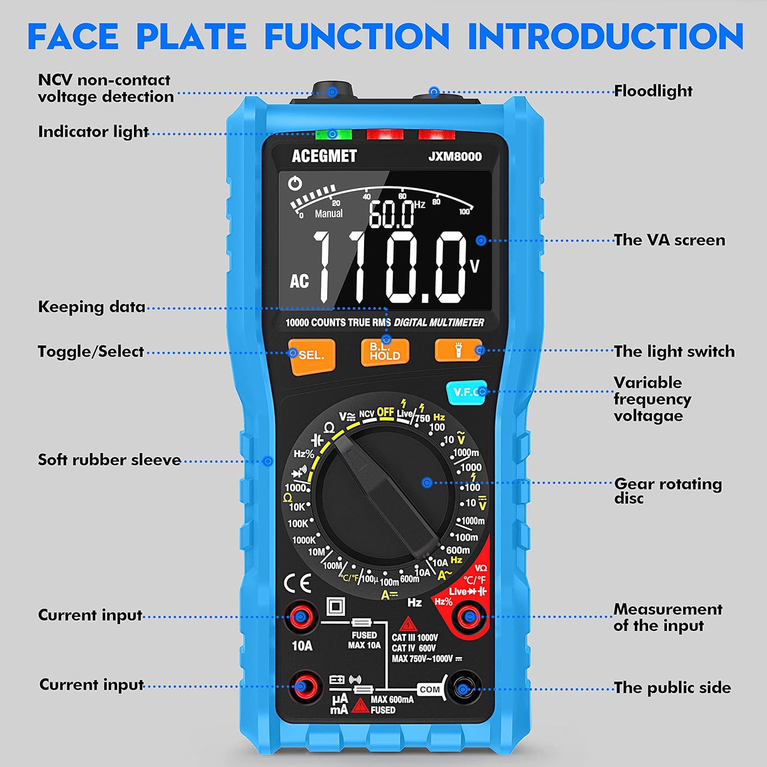
Rycina 3.1: Przód view of the Acegmet JXM8000 Digital Multimeter with labeled components.
- VA Screen: Large LCD display for measurement readings, units, and indicators.
- Kontrolka: Provides visual feedback for certain functions, such as NCV.
- Flesz: Located at the top, activated by the light switch for illumination in dark areas.
- SEL. Button (Toggle/Select): Służy do przełączania między różnymi trybami pomiaru przy pomocy jednego położenia przełącznika obrotowego (np. AC/DC, dioda/ciągłość).
- HOLD Button (Keeping Data): Zamraża aktualny odczyt na wyświetlaczu. Naciśnij ponownie, aby zwolnić.
- V.F.C Button (Variable Frequency Voltagmi): Aktywuje tryb pomiaru kontroli zmiennej częstotliwości.
- Gear Rotating Disc: The central rotary switch used to select the desired measurement function.
- Gniazda wejściowe: Ports for connecting test leads. These include common (COM), voltage/resistance/frequency/capacitance (VΩHznF), and current (mA/10A) inputs.
- Soft Rubber Sleeve: A protective outer casing designed to prevent accidental electric shock and provide durability.
3.2 Główne cechy
- Prawdziwa wartość skuteczna (TRMS): Dokładnie mierzy objętość prądu przemiennegotage and current for non-sine wave signals.
- Zakres automatyczny/ręczny: Offers flexibility for both automatic range selection and manual range control.
- Objętość bezkontaktowatage (NCV) Wykrywanie: Wykrywa objętość ACtage bez kontaktu fizycznego.
- Test linii na żywo: Identyfikuje przewody pod napięciem.
- Pomiar temperatury: Mierzy temperaturę w stopniach Celsjusza i Fahrenheita.
- Wyświetlanie 10000 zliczeń: Provides high-resolution readings.
- Przechowywanie danych: Zamraża wyświetlany pomiar.
- Automatyczne wyłączanie: Urządzenie wyłącza się automatycznie po 15 minutach bezczynności w celu oszczędzania baterii.
- Wskaźnik niskiego poziomu naładowania baterii: Ostrzega, gdy baterie wymagają wymiany.
4. Konfiguracja
4.1 Instalacja baterii
The multimeter requires 2 x AA 1.5V batteries. To install or replace batteries:
- Upewnij się, że multimetr jest wyłączony i przewody pomiarowe są odłączone.
- Carefully remove the soft rubber sleeve.
- Znajdź pokrywę komory baterii z tyłu urządzenia.
- Odkręć śrubę(y) mocującą(e) i zdejmij pokrywę.
- Insert the 2 x AA batteries, observing correct polarity (+/-).
- Załóż pokrywę komory baterii i zabezpiecz ją śrubą(ami).
- Reinstall the soft rubber sleeve.
4.2 Podłączanie przewodów pomiarowych
Always connect the black test lead to the "COM" (Common) jack. Connect the red test lead to the appropriate input jack based on the desired measurement:
- dla objtage, Resistance, Frequency, Capacitance, Diode, and Continuity measurements, connect the red lead to the "VΩHznF" jack.
- For Current measurements (up to 600mA), connect the red lead to the "mA" jack.
- For High Current measurements (up to 10A), connect the red lead to the "10A" jack.
Ensure test leads are fully inserted into the jacks before taking measurements.
5. Instrukcja obsługi
5.1 Włączanie/wyłączanie zasilania
To power on the multimeter, rotate the gear rotating disc from the "OFF" position to any desired measurement function. To power off, rotate the disc back to the "OFF" position.
5.2 Automatyczne i ręczne ustawianie zakresu

Figure 5.1: Rotary switch indicating Automatic and Manual Ranging sections.
- Funkcja automatycznego zakresu: When the rotary switch is set to the "AUTOMATIC RANGE" section, the multimeter automatically selects the appropriate measurement range for AC/DC voltage, resistance, capacitance, frequency, on/off (continuity), and diode tests. This simplifies operation.
- Manual Range Function: When the rotary switch is set to the "MANUAL RANGE" section, you can manually select specific ranges for NCV, Live wire identification, AC/DC voltage, AC/DC current, temperature, and resistance measurements. This provides greater control for experienced users.
5.3 Pomiary szczegółowe
W przypadku większości pomiarów należy postępować zgodnie z poniższymi ogólnymi krokami:
- Connect test leads correctly as described in Section 4.2.
- Rotate the gear rotating disc to the desired measurement function.
- If multiple functions are available at one position (e.g., AC/DC voltage), press the "SEL." button to toggle between them.
- Apply the test leads to the circuit or component under test.
- Read the measurement value on the VA screen.
5.3.1 objtagPomiary (prąd przemienny/stały)
Set the rotary switch to the 'V' (Voltage) position. Use the 'SEL.' button to switch between AC (~) and DC ( ) voltage. Connect test leads in parallel with the circuit or component.
5.3.2 Pomiar prądu (AC/DC)
Set the rotary switch to the 'A' (Current) position. Use the 'SEL.' button to switch between AC (~) and DC ( ) current. Connect test leads in series with the circuit. Ensure the correct input jack (mA or 10A) is used.
5.3.3 Pomiar rezystancji (Ω)
Set the rotary switch to the 'Ω' (Resistance) position. Connect test leads across the component. Ensure the circuit is de-energized before measuring resistance.
5.3.4 Test ciągłości
Set the rotary switch to the 'Ω' (Resistance) position and press 'SEL.' until the continuity symbol ( ) is displayed. A continuous beep indicates a low-resistance path (continuity).
5.3.5 Test diody
Set the rotary switch to the 'Ω' (Resistance) position and press 'SEL.' until the diode symbol ( ) is displayed. Connect the red lead to the anode and the black lead to the cathode of the diode. The forward voltagZostanie wyświetlona kropla.
5.3.6 Capacitance Measurement (nF/µF/mF)
Set the rotary switch to the 'nF' (Capacitance) position. Connect test leads across the capacitor. Ensure the capacitor is discharged before testing.
5.3.7 Pomiar częstotliwości (Hz)
Set the rotary switch to the 'Hz' (Frequency) position. Connect test leads to the signal source.
5.3.8 Pomiar temperatury (°C/°F)

Figure 5.2: Multimeter demonstrating NCV, Live Line, and Temperature testing functions.
Set the rotary switch to the '°C/°F' (Temperature) position. Connect the included K-type thermocouple probe to the input jacks (usually VΩHznF and COM). Place the probe tip on or near the object whose temperature is to be measured. Press 'SEL.' to switch between Celsius and Fahrenheit.
5.3.9 tom bez kontaktutage (NCV) Wykrywanie
Set the rotary switch to the 'NCV' position. Move the top of the multimeter near an AC voltage source. The indicator light will flash, and an audible beep will sound, with the frequency of beeps increasing as the multimeter gets closer to the voltagŹródło.
5.3.10 Live Line Test
Set the rotary switch to the 'Live' position. Insert the red test lead into the 'VΩHznF' jack. Touch the red test lead to the conductor to be tested. The display will indicate 'LIVE' and an audible alarm will sound if a live wire is detected.
5.4 Funkcja zatrzymania danych
Press the "HOLD" button to freeze the current reading on the display. Press it again to release the hold function and resume live readings.
5.5 Podświetlenie i latarka
Press the light switch button (often integrated with the HOLD button or a separate button) to turn on the display backlight for better visibility in low-light conditions. A long press may activate the flashlight located at the top of the multimeter.
6. Konserwacja
6.1 Czyszczenie
Wytrzyj multimetr casing z reklamąamp cloth and mild detergent. Do not use abrasive cleaners or solvents. Ensure the device is powered off and disconnected from all circuits before cleaning.
6.2 Wymiana baterii
When the low battery indicator appears on the display, replace the batteries as described in Section 4.1. Remove batteries if the multimeter will not be used for an extended period.
6.3 Wymiana bezpiecznika

Rysunek 6.1: Wewnętrzne view highlighting fuse protection.
If a fuse blows (indicated by "FUSE" on the display and an alarm), it must be replaced with a fuse of the same type and rating. The JXM8000 uses fast-blow ceramic fuses. Refer to the specifications for correct fuse ratings.
- Upewnij się, że multimetr jest wyłączony i wszystkie przewody pomiarowe są odłączone.
- Carefully remove the soft rubber sleeve.
- Unscrew the screws securing the back casing and carefully open the multimeter.
- Zlokalizuj przepalony bezpiecznik(i) i ostrożnie go wyjmij.
- Zamontuj nowe bezpieczniki właściwego typu i o właściwych parametrach.
- Carefully reassemble the multimeter, ensuring all screws are tightened.
- Reinstall the soft rubber sleeve.
6.4 Przechowywanie
Store the multimeter in a cool, dry place, away from direct sunlight and extreme temperatures. If storing for an extended period, remove the batteries.
7. Rozwiązywanie Problemów
- Display shows "LEAD" and beeps: This indicates incorrect test lead connection for the selected function. Reconnect the test leads to the appropriate input jacks.
- Na wyświetlaczu pojawia się „OL”: This indicates an overload condition, meaning the measured value exceeds the selected range or the multimeter's maximum capacity. Switch to a higher range (if in manual mode) or ensure the measurement is within the device's limits.
- Multimetr się nie włącza: Sprawdź instalację baterii i upewnij się, że nie są rozładowane. W razie potrzeby wymień je.
- Niedokładne odczyty: Check battery level, ensure test leads are properly connected, and verify the correct measurement function and range are selected. Clean test lead tips if corroded.
- Brak sygnału dźwiękowego: Upewnij się, że obwód jest odłączony od napięcia. Sprawdź przewody pomiarowe pod kątem uszkodzeń.
8. Specyfikacje
| Parametr | Specyfikacja |
|---|---|
| Maksymalny wyświetlacz | 9999 liczy |
| Wybór zakresu | Automatic & Manual Range |
| Prędkość pomiaru | 10 razy / sekundę |
| Wyświetlacz przeciążenia | Wyświetlacz OL |
| Wrong Insert Alarm | Display LEAD |
| Test włączania/wyłączania | Brzęczyk |
| NCV/VFC Function | Tak |
| Test linii na żywo | Tak |
| Funkcja zatrzymania danych | Tak |
| Wskaźnik niskiego poziomu naładowania baterii | Tak |
| Automatyczne wyłączanie | 15 minut |
| Zasilacz | 2 baterie AA 1.5 V |
| Klasa bezpieczeństwa | IEC61010 CAT.600V CAT IV, 1000V CAT.III |
| Zakres prądu AC | 99.99mA/600mA ±(1.0% + 3); 10A (1.5% + 3) |
| AC Objętośćtage Zakres | 999.9mV/9.999V/99.99V ± (0.8%+3); 750V ± (1.0%+5) |
| Objętość DCtage Zakres | 999.9mV/9.999V/99.99V/999.9V ± (0.5%+3) |
| Zakres prądu stałego | 99.99µA/999.9mA/600mA ±(0.8% + 3); 10A (1.2% + 3) |
| Zakres oporu | 999.9Ω/9.999KΩ/99.99KΩ/999.9KΩ/9.999MΩ ± (0.8%+32); 99.99MΩ ± (1.2%+5) |
| Zakres pojemności | 9.999nF ±(4.0% + 30); 99.99nF/999.9nF/9.999µF/99.99µF/999.9µF/9.999mF/99.99mF ±(4.0% + 3) |
| Zakres częstotliwości | 9.999Hz/99.99Hz/999.9Hz/9.999kHz/99.99kHz/999.9kHz/9.999MHz ±(1.0%+3) |
| Zakres temperatur | -4℉-1832℉ / -20℃-1000℃ ±(1.0%+3) |
9. Gwarancja i wsparcie
The Acegmet JXM8000 Digital Multimeter comes with an 18-month warranty from the date of purchase. This warranty covers defects in materials and workmanship under normal use. It does not cover damage caused by misuse, accident, unauthorized modification, or neglect.
For technical support, warranty claims, or service inquiries, please contact Acegmet customer service through the retailer's platform or the official Acegmet website. Please have your purchase receipt and product model number (JXM8000) available when contacting support.