
1. Koniec produktuview
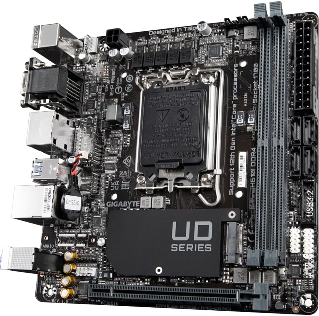
The GIGABYTE H610I DDR4 is a Mini-ITX motherboard designed to support 12th Generation Intel Core Series Processors. It offers a robust platform for building compact yet powerful systems, suitable for various applications from gaming to everyday computing. This motherboard integrates essential features for reliable performance and connectivity.
Główne cechy:
- Gniazdo Intel LGA 1700: Obsługuje procesory Intel Core 12. generacji.
- Kompatybilność z DDR4: Features Dual Channel Non-ECC Unbuffered DDR4 memory support with 2 DIMM slots.
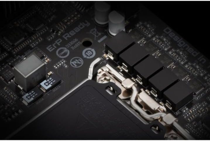
- Dominująca konstrukcja mocy: Equipped with a 4+1+1 Hybrid Digital VRM Design for stable power delivery.
- Zaawansowana łączność: Includes PCIe 4.0 support, a Single NVMe PCIe 3.0 x4 M.2 slot, and USB 3.2 Gen1 ports.
- Szybkie sieciowanie: Integrated Intel GbE LAN Chip for reliable wired network connections.
- Dynamiczny dźwięk: Features High Quality Audio Capacitors and Audio Noise Guard for enhanced sound experience.


2. Konfiguracja i instalacja
Follow these steps for proper installation of your GIGABYTE H610I DDR4 motherboard and its components.
2.1 Instalacja procesora
- Znajdź gniazdo procesora LGA 1700 na płycie głównej.
- Otwórz dźwignię gniazda procesora i zdejmij osłonę ochronną.
- Carefully align your 12th Gen Intel Core processor with the socket, ensuring the notches on the CPU match the keys on the socket.
- Ostrożnie umieść procesor w gnieździe, nie używając siły.
- Zamknij dźwignię gniazda procesora, aby zabezpieczyć procesor.

2.2 Instalowanie pamięci DDR4
- Znajdź dwa gniazda DDR4 DIMM na płycie głównej.
- Otwórz zaciski na obu końcach gniazda DIMM.
- Dopasuj wycięcie na module pamięci DDR4 do wypustki w gnieździe DIMM.
- Wsuń moduł pamięci mocno do gniazda, aż zatrzaski zatrzasną się na miejscu.
2.3 Installing NVMe M.2 SSD
- Locate the single NVMe PCIe 3.0 x4 M.2 slot.
- Odkręć śrubę M.2 i zdejmij podkładkę z płyty głównej.
- Włóż dysk SSD M.2 do gniazda pod kątem.
- Gently push down the M.2 SSD and secure it with the screw and standoff.
2.4 Połączenia zasilania
- Podłącz 24-pinowe złącze zasilania ATX zasilacza do odpowiedniego złącza na płycie głównej.
- Connect the 8-pin CPU power connector (or 4-pin if applicable) to the CPU power header.
2.5 Panel przedni i połączenia urządzeń peryferyjnych
Connect your case's front panel headers (power button, reset button, USB, audio) to the corresponding pins on the motherboard. Refer to your case manual for specific pin layouts. Connect peripherals such as USB devices, display cables, and network cables to the rear I/O ports.
3. Instrukcja obsługi
3.1 Początkowe uruchomienie i konfiguracja BIOS-u/UEFI
- Po zmontowaniu wszystkich elementów podłącz monitor, klawiaturę i mysz.
- Power on your system. During the boot process, press the USUNĄĆ Naciskaj klawisz wielokrotnie, aby wejść do narzędzia konfiguracji BIOS/UEFI.
- In the BIOS/UEFI, you can configure boot order, system time, and other advanced settings. Save changes and exit to continue booting into your operating system installer.
3.2 Instalacja sterownika
After installing your operating system, install the necessary drivers for the motherboard components. These typically include chipset drivers, LAN drivers, audio drivers, and any other peripheral drivers. Drivers can usually be found on the GIGABYTE official webwitryna dla konkretnego modelu płyty głównej.
4. Konserwacja
4.1 Czyszczenie
Regularnie czyść wnętrze komputera, aby zapobiec gromadzeniu się kurzu, który może prowadzić do przegrzewania i spadku wydajności. Użyj sprężonego powietrza, aby usunąć kurz z wentylatorów, radiatorów i innych podzespołów. Przed czyszczeniem upewnij się, że system jest wyłączony i odłączony od zasilania.
4.2 Aktualizacje BIOS-u/UEFI
Okresowo sprawdzaj GIGABYTE website for BIOS/UEFI updates. Updates can improve system stability, add support for new hardware, or fix bugs. Follow the instructions provided by GIGABYTE carefully when performing a BIOS/UEFI update to avoid system damage.
5. Rozwiązywanie Problemów
W tej sekcji opisano typowe problemy, jakie mogą wystąpić w przypadku płyty głównej.
5.1 Brak wyjścia wyświetlacza
- Sprawdź połączenie monitora: Ensure your monitor is correctly connected to the graphics card or motherboard's integrated graphics port and is powered on.
- Verify RAM Installation: Reseat the DDR4 memory modules firmly in their slots. Incorrectly seated RAM is a common cause of no display.
- Moc procesora: Confirm the 8-pin (or 4-pin) CPU power connector is securely plugged into the motherboard.
- Karta graficzna: If using a dedicated graphics card, ensure it is properly seated in the PCIe slot and has all necessary power cables connected.
- Wygięte piny procesora: Carefully inspect the CPU socket for any bent pins. If found, contact GIGABYTE support.
5.2 System Unresponsive / Does Not Boot
- Zasilanie: Ensure the power supply is connected to the motherboard (24-pin ATX and CPU power) and is switched on.
- Wyczyść pamięć CMOS: Try clearing the CMOS (Complementary Metal-Oxide-Semiconductor) settings. This can usually be done by removing the CMOS battery for a few minutes or using a dedicated jumper on the motherboard.
- Minimal Boot Configuration: Odłącz wszystkie nieistotne urządzenia peryferyjne i podzespoły (np. dodatkowe dyski, karty rozszerzeń) i spróbuj uruchomić komputer tylko przy użyciu procesora, jednej kości pamięci RAM i karty graficznej (jeśli nie posiada zintegrowanej karty graficznej).
5.3 RAM Slot Malfunction
- If one of the two DDR4 RAM slots is not functioning, try testing each RAM stick individually in each slot to isolate the faulty component (RAM stick or motherboard slot).
- Ensure the RAM is compatible with the motherboard's specifications (DDR4, Non-ECC Unbuffered).
6. Specyfikacje techniczne
| Funkcja | Specyfikacja |
|---|---|
| Marka | GIGABAJT |
| Nazwa modelu | Pamięć DDR610 H4I |
| Gniazdo procesora | LGA 1700 |
| Kompatybilne procesory | Procesory Intel Core serii 12. generacji |
| Typ chipsetu | Intel H610 |
| Technologia pamięci RAM | DDR4 (dwukanałowa, niebuforowana, bez ECC) |
| Gniazda pamięci | 2 moduły DIMM |
| Prędkość zegara pamięci | Do 3200 MHz |
| Sloty PCIe | PCIe4.0 |
| Gniazda M.2 | 1 x NVMe PCIe 3.0 x4 M.2 |
| Porty USB | USB 3.2 Gen1, USB 2.0 |
| Sieć lokalna | Intel GbE LAN Chip |
| Audio | Wysokiej jakości kondensatory audio i ochrona przed zakłóceniami audio |
| Współczynnik kształtu | Mini-ITX |
| Wymiary produktu | 8.74 x 7.09 x 2.56 cala |
| Waga przedmiotu | 1.3 funta |
7. Filmy produktowe
7.1 Film demonstracyjny produktu
This video provides a brief demonstration of the GIGABYTE H610I DDR4 Mini-ITX Motherboard, showcasing its physical features and design. (Duration: 0:35)
7.2 Produkt powyżejview Wideo
Urzędnik ponadview video detailing the features and benefits of the GIGABYTE H610I DDR4 Mini-ITX Motherboard. (Duration: 0:52)
8. Gwarancja i wsparcie
8.1 Informacje o gwarancji
GIGABYTE products are covered by a limited warranty. The specific terms and duration of the warranty may vary by region and product type. Please refer to the warranty card included with your product or visit the official GIGABYTE webStrona zawiera szczegółowe informacje o gwarancji.
8.2 Wsparcie techniczne
Aby uzyskać pomoc techniczną, pobrać sterowniki lub uzyskać więcej informacji o produkcie, odwiedź oficjalną stronę pomocy technicznej GIGABYTE webNa stronie znajdziesz często zadawane pytania, poradniki rozwiązywania problemów i dane kontaktowe do działu obsługi klienta.
Oficjalny GIGABYTE Webstrona: www.gigabyte.com


