
1. Wprowadzenie
This manual provides detailed instructions for the installation, operation, and maintenance of your AMKI 3-Channel DMX512 Decoder. This device is designed to convert universal DMX512 digital signals into PWM signals, allowing it to drive LED lighting products such as RGB LED strips, modules, and other LED fixtures. It features a digital display for easy address setting and mode selection.
2. Informacje dotyczące bezpieczeństwa
- Upewnij się, że napięcie zasilaniatage matches the decoder's requirements (DC12V-24V).
- Do not connect the decoder to AC power directly.
- Przed przystąpieniem do wykonywania jakichkolwiek podłączeń lub regulacji należy zawsze odłączyć zasilanie.
- Unikaj narażania urządzenia na działanie wilgoci lub ekstremalnych temperatur.
- Nie należy podejmować prób otwierania lub modyfikowania urządzenia, gdyż spowoduje to utratę gwarancji i może spowodować uszkodzenia lub obrażenia.
- Aby zapobiec przegrzaniu, należy zapewnić odpowiednią wentylację.
3. Koniec produktuview
The AMKI 3-Channel DMX512 Decoder is a compact and robust unit designed for reliable DMX control of LED lighting. It features a digital display for easy configuration and multiple input/output options.

Rycina 3.1: Przód view of the AMKI 3-Channel DMX512 Decoder, showing the digital display, control buttons, and XLR input/output ports.
3.1 Elementy sterujące i połączenia na panelu przednim

Rysunek 3.2: Szczegółowy view of the front panel, highlighting the numerical display, status display (A/H/S), control buttons, and DMX512 IN/OUT XLR interfaces.
- Wyświetlacz numeryczny: Shows the current DMX address or selected mode/speed.
- Status Display (A/H/S): Indicates the current operating mode (Address, Mode, Speed).
- Control Buttons (- / + / SET): Used to navigate menus, adjust values, and confirm settings.
- DMX512 IN/OUT (XLR): Standard 3-pin XLR connectors for DMX signal input and output.
3.2 Połączenia panelu tylnego
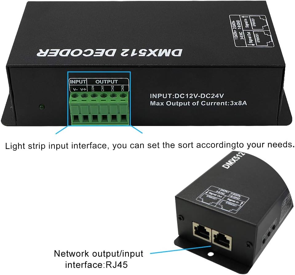
Rysunek 3.3: Szczegółowy view of the rear panel, showing the DC12V-DC24V power input, 3-channel output terminals, and RJ45 network input/output interfaces.
- INPUT: DC12V-DC24V: Power input terminals for connecting a compatible DC power supply.
- OUTPUT: CH1, CH2, CH3: Three output channels for connecting LED lighting products. Each channel supports up to 8A.
- Network Output/Input Interface (RJ45): RJ45 ports for DMX signal input and output, wired with standard DMX pin locations.
4. Konfiguracja i instalacja
Follow these steps to properly install and connect your DMX512 Decoder.
4.1 Schemat okablowania

Figure 4.1: Typical connection diagram for the DMX512 Decoder, illustrating connections from a DMX console, power supply, and to high-power LED lamps.
4.2 Kroki połączenia
- Podłączenie zasilania: Connect a DC12V-24V power supply to the "INPUT: DC12V-DC24V" terminals. Ensure correct polarity (V+ to positive, V- to negative). The maximum output current is 3x8A, so ensure your power supply can handle the total load of your LED lights.
- LED Output Connection: Connect your LED lighting products (e.g., RGB LED strips) to the "OUTPUT: CH1, CH2, CH3" terminals. For RGB strips, connect Red to CH1, Green to CH2, Blue to CH3, and the common anode to V+. For single-color lights, connect to any channel. Ensure the total current for each channel does not exceed 8A.
- DMX Signal Input:
- Połączenie XLR: Connect your DMX controller's output to the "DMX512 IN" XLR port. If daisy-chaining multiple decoders, connect the "DMX512 OUT" of the first decoder to the "DMX512 IN" of the next.
- Połączenie RJ45: Alternatively, use a Cat5 Ethernet cable to connect your DMX controller to the RJ45 input port. The RJ45 ports are wired for standard DMX pin locations.
- Włączanie: Once all connections are secure, apply power to the decoder. The digital display will illuminate.
5. Instrukcja obsługi
The AMKI DMX512 Decoder offers DMX mode and several built-in static/dynamic modes. The digital display and buttons are used for configuration.
5.1 Setting DMX Address (A Mode)
In DMX mode, the decoder responds to DMX signals starting from a specific address. This is the default operating mode.
- When powered on, the display will typically show an 'A' followed by a four-digit number (e.g., A001). This indicates the current DMX start address.
- Naciśnij USTAWIĆ button to enter address setting mode. The digits will flash.
- Użyj + I - buttons to adjust the DMX start address (range A001 to A512).
- Naciśnij USTAWIĆ button again to confirm and save the address. The display will stop flashing.
- The decoder will now respond to DMX signals on the set address and the subsequent two channels (for a 3-channel device). For example, if set to A001, it will use DMX channels 1, 2, and 3.
5.2 Built-in Modes (H Mode)
The decoder includes pre-programmed static and dynamic lighting effects. These modes disable DMX control.
- From DMX address setting mode (A mode), press the USTAWIĆ button repeatedly until the display shows 'H' followed by a two-digit number (e.g., H-01). This indicates the built-in mode selection.
- Użyj + I - buttons to cycle through the available built-in modes (H-01 to H-11). Each mode represents a different static color or dynamic effect.
- Naciśnij USTAWIĆ button to confirm the selected mode.
5.3 Adjusting Speed/Brightness (S Mode)
For dynamic built-in modes, you can adjust the speed. For static built-in modes, this may adjust brightness.
- While in a built-in mode (H mode), press the USTAWIĆ button again until the display shows 'S' followed by a two-digit number (e.g., S-01). This indicates speed/brightness adjustment.
- Użyj + I - buttons to adjust the speed or brightness level (S-01 to S-20).
- Naciśnij USTAWIĆ przycisk aby potwierdzić ustawienie.
Note: To return to DMX control, you must manually set the device back to 'A' mode and select a DMX address. The device will retain its last setting upon power cycle.
6. Konserwacja
- Utrzymuj urządzenie w czystości i zapobiegaj jego zakurzaniu. Do czyszczenia używaj miękkiej, suchej ściereczki.
- Upewnij się, że wszystkie połączenia są pewne i wolne od korozji.
- Store the device in a dry, cool environment when not in use.
- No user-serviceable parts inside. Refer all servicing to qualified personnel.
7. Rozwiązywanie Problemów
| Problem | Możliwa przyczyna | Rozwiązanie |
|---|---|---|
| Diody LED nie świecą się. |
|
|
| LEDs are on but not responding to DMX controller. |
|
|
| Display dims or unit stops responding to buttons. |
|
|
| Difficulty connecting wires to terminals. | Terminals are small for large gauge wires. | Use appropriate wire gauge for the current draw. If necessary, use smaller gauge wire with ferrules or consider professional installation for high current applications. |
8. Specyfikacje
| Funkcja | Szczegół |
|---|---|
| Numer modelu | 3CH DMX-8AD |
| Wejście Voltage | Prąd stały 12 V-prąd stały 24 V |
| Kanały wyjściowe | 3 kanały |
| Maksymalny prąd wyjściowy | 8A per channel (Total 24A) |
| Moc wyjściowa | 288 W (12 V) / 576 W (24 V) |
| Kanały sterowania DMX | 3 kanałów DMX |
| Interfejs DMX | 3-pin XLR (IN/OUT), RJ45 (IN/OUT) |
| Tryb sterowania | DMX512, Stand-alone (built-in modes) |
| Wyświetlacz | Cyfrowy wyświetlacz LED |
| Wymiary (dł. x szer. x wys.) | 166mm x 67mm x 41mm (6.5 x 2.6 x 1.6 cale) |
| Waga | Około 13.7 uncji (388 g) |
| Temperatura pracy | -20°C do 60°C |

Figure 8.1: Physical dimensions of the DMX512 Decoder.
9. Gwarancja i wsparcie
AMKI products are designed for reliability and performance. For warranty information, technical support, or service inquiries, please contact your retailer or the manufacturer directly. Please have your product model number (3CH DMX-8AD) and purchase details available when contacting support.
Aby uzyskać dalszą pomoc, odwiedź stronę AMKI Store on Amazon.