
Yanmis DSE5110
Yanmis DSE5110 Generator Controller Module User Manual
Model: DSE5110
1. Koniec produktuview
The Yanmis DSE5110 Generator Controller Module is an advanced microprocessor-controlled unit designed for automatic start-up and monitoring of generator sets. It features a clear LCD display for real-time parameter monitoring and incorporates various protection functions to ensure reliable operation.
Główne cechy:
- Wyświetlacz LCD: 132 x 64 pixel LCD for easy data readability and accurate time display.
- Automatic Start-Up: Microprocessor control for multi-function engine automatic start-up.
- Monitorowanie na żywo: Wyświetla trójfazową objętośćtage, three-phase current, unit frequency, cooling water temperature, oil pressure, engine speed, battery voltage, accumulative running time, and fault reasons.
- Configurable Cycles: Multiple start and stop cycles can be preset.
- Przypomnienie o konserwacji: Preset maintenance cycle reminder function.
- Zdalne monitorowanie: Capable of remote monitoring through the network (with DSE855).
- Funkcje ochronne: Includes protection against generator overspeed/underspeed, low oil pressure, high water temperature, start failure, emergency stop, speed loss, and charging failure.
- Zgodność systemu: Compatible with intelligent building systems (BMS).
- IP65 Class: IP65 protection class (requires matching gasket).
- Ustawienia regulowane: Allows setting start time, frequency, remote start, auto-record stop fault, and query functions.
- Bezpieczeństwo: System password lock function for enhanced security.

Rycina 1.1: Przód view of the DSE5110 Generator Controller Module, showing the LCD display, control buttons, and included mounting screws.

Rysunek 1.2: Kątowy view of the DSE5110 controller, highlighting the LCD screen's detailed display capabilities and the side connection ports.
2. Specyfikacje
| Atrybut | Wartość |
|---|---|
| Model | DSE5110 |
| Typ wyświetlacza | Wyświetlacz LCD 132 x 64 pikseli |
| Klasa ochrony | IP65 (with matching gasket) |
| Uruchom wyjście przekaźnikowe | 16Amp Objętość układu DCtage |
| Wyjście przekaźnika paliwa | 16Amp Objętość układu DCtage |
| Pomocnicze wyjście przekaźnikowe | 5Amp Objętość układu DCtage |
| Waga przedmiotu | 1.85 funta |
| Producent | Yanmis |
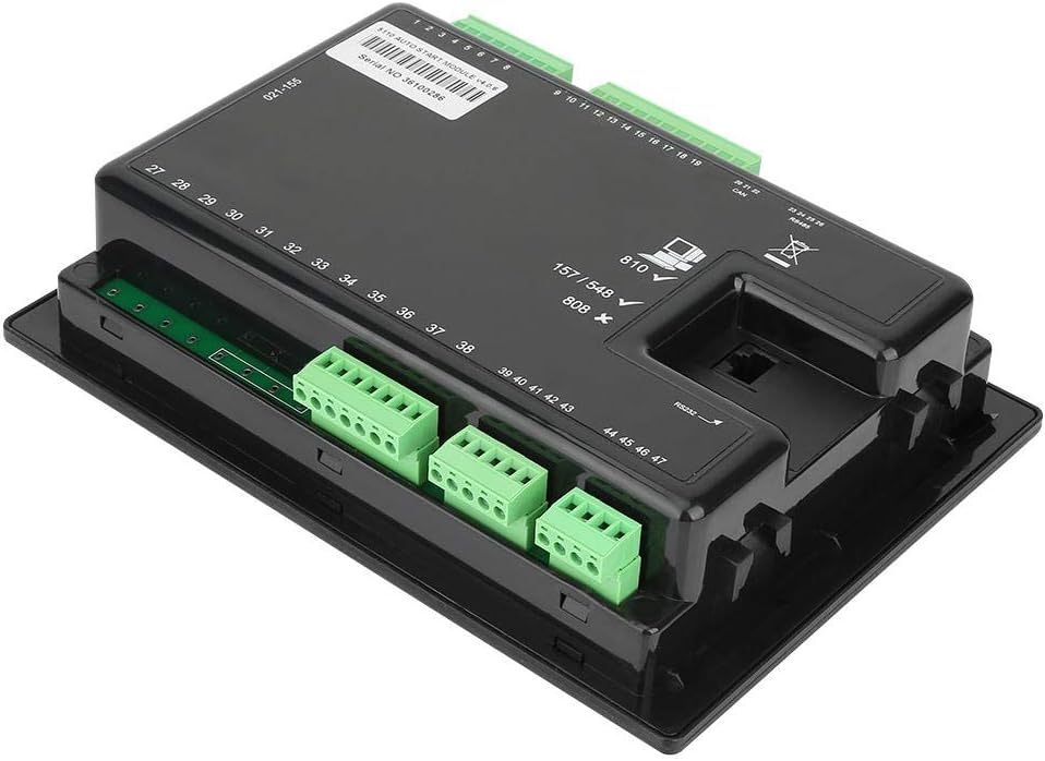
Rysunek 2.1: Tył view of the DSE5110 controller, illustrating the various connection terminals for power, sensors, and control signals.
3. Konfiguracja i instalacja
Proper installation is crucial for the safe and effective operation of the DSE5110 controller. It should be mounted in a secure location, typically within a control panel, ensuring adequate ventilation and protection from environmental elements.
3.1 Montaż kontrolera
The controller is designed for panel mounting. Use the provided mounting screws and brackets to secure the unit. Ensure the panel cutout matches the dimensions of the controller for a snug fit and to achieve the specified IP65 protection rating when a gasket is used.

Rysunek 3.1: Zbliżenie view of the mounting screws and clips used to secure the DSE5110 controller to a panel.
3.2 Połączenia elektryczne
Connect the generator's wiring to the appropriate terminals on the rear of the DSE5110 module. This includes connections for three-phase voltage, three-phase current, battery voltage, oil pressure sensor, water temperature sensor, engine speed sensor, and control signals for start, fuel, and auxiliary functions. Refer to the wiring diagram provided with your generator set and the DSE5110 for specific terminal assignments.
- Zasilanie: Podłącz zasilacz prądu stałego do wyznaczonych zacisków.
- Wejścia generatora: Połącz objętośćtage and current transformers (CTs) as per the system requirements.
- Czujniki silnika: Connect oil pressure, water temperature, and speed sensors.
- Wyjścia sterujące: Connect the start, fuel, and auxiliary relay outputs to the generator's control circuits.
- Porty komunikacyjne: Utilize the RS232/RS485 ports for PC configuration or remote monitoring (DSE855).

Rysunek 3.2: Szczegółowy widok z tyłu view of the DSE5110 controller, showing the serial number, various numbered terminals for wiring, and communication ports (CAN, RS485, RS232).
4. Instrukcja obsługi
The DSE5110 controller offers both manual and automatic operation modes, along with remote start capabilities. The LCD display provides comprehensive real-time data for easy monitoring.
4.1 Układ panelu sterowania
The front panel features an LCD display and several control buttons:
- Wyświetlacz LCD: Shows various generator parameters and status messages.
- Stop/Reset Button (Red 'O'): Stops the generator and resets any active alarms.
- Manual Start Button (Hand icon): Initiates a manual start sequence.
- Increase/Decrease Buttons (+/-): Służy do poruszania się po menu i zmieniania ustawień.
- Auto Mode Button (Auto icon): Puts the controller into automatic mode, allowing for remote or scheduled starts.
- Przycisk Start (zielony „I”): Initiates the generator start sequence in manual mode.

Rysunek 4.1: Przód kątowy view of the DSE5110 controller, clearly showing the LCD screen and the array of control buttons for operation.
4.2 Uruchamianie generatora
- Rozpoczęcie ręczne: Naciśnij Przestają zresetować button to ensure the controller is in a stopped state. Then, press the Ręczny start button. The controller will initiate the start sequence.
- Automatyczny start: Naciśnij Tryb automatyczny button. The controller will now respond to remote start signals or pre-programmed events (e.g., mains failure).
- Zdalne uruchamianie: Ensure the controller is in Tryb automatyczny. A remote start signal (e.g., from a transfer switch or BMS) will trigger the generator to start.
4.3 Parametry monitorowania
The LCD display provides real-time data. Use the Zwiększyć/zmniejszyć buttons to scroll through different screens and view parameters such as:
- Objętość trójfazowatage (L1, L2, L3)
- Prąd trójfazowy
- Unit frequency
- Temperatura wody chłodzącej
- Ciśnienie oleju
- Prędkość obrotowa silnika (obr./min)
- Pojemność bateriitage
- Łączny czas pracy
- Active fault reasons
5. Konserwacja
Regular maintenance ensures the longevity and reliable performance of your DSE5110 controller and the generator set it manages.
- Czyszczenie: Keep the controller's display and buttons clean using a soft, dry cloth. Avoid abrasive cleaners or solvents.
- Znajomości: Periodically check all electrical connections for tightness and signs of corrosion. Loose connections can lead to erratic behavior or damage.
- Aktualizacje oprogramowania układowego: Sprawdź producenta webodwiedź tę witrynę, aby sprawdzić, czy są dostępne aktualizacje oprogramowania sprzętowego, które mogą poprawić wydajność lub dodać nowe funkcje.
- Przypomnienia o konserwacji: The DSE5110 has a preset maintenance cycle reminder function. Ensure this is configured to align with your generator's service schedule.
- Kontrola środowiskowa: Ensure the operating environment remains within specified temperature and humidity ranges. Verify the IP65 seal (if gasket is used) is intact.
6. Rozwiązywanie Problemów
The DSE5110 controller is equipped with various protection functions and fault indicators to assist in troubleshooting. When a fault occurs, the LCD will display a fault reason, and the generator may shut down or issue a warning.
Typowe błędy i rozwiązania:
| Wskazanie błędu | Możliwa przyczyna | Działanie |
|---|---|---|
| Generator Overspeed/Underspeed | Engine speed outside normal operating range. | Check engine governor settings. Inspect speed sensor and wiring. |
| Niskie ciśnienie oleju | Insufficient engine oil or faulty oil pressure sensor. | Check engine oil level. Inspect oil pressure sensor and wiring. |
| Wysoka temperatura wody | Przegrzanie silnika. | Check coolant level, radiator, fan, and water temperature sensor. |
| Start Failure | Generator fails to start after multiple attempts. | Check fuel supply, battery voltage, starter motor, and engine pre-heat system. |
| Zatrzymanie awaryjne | Emergency stop button activated or wiring fault. | Ensure emergency stop button is disengaged. Check emergency stop circuit wiring. |
| Awaria ładowania | Alternator not charging battery. | Check alternator, charging circuit wiring, and battery condition. |
Zawsze naciskaj Przestają zresetować button after resolving a fault to clear the alarm and allow the controller to resume normal operation.
7. Gwarancja i wsparcie
Yanmis products are designed for reliability and performance. For warranty information, technical support, or service inquiries, please refer to the contact details provided with your purchase or visit the official Yanmis webstrona.
Please retain your proof of purchase for warranty claims. Unauthorized modifications or repairs may void the warranty.
Ask a question about this manual
Ask about setup, troubleshooting, compatibility, parts, safety, or missing instructions. Manuals+ will review the question and use this page’s manual context to help answer it.