1. Wprowadzenie
This manual provides essential information for the safe and efficient installation, operation, and maintenance of your Dieffematic PM1 400 Irreversible Swing Gate Automation Kit. This kit is designed for automating double-leaf swing gates, suitable for residential and condominium use. Please read all instructions carefully before beginning installation or operation.
2. Instrukcje bezpieczeństwa
- Installation must be performed by qualified personnel in compliance with local safety regulations.
- Przed przystąpieniem do prac konserwacyjnych lub regulacyjnych należy odłączyć zasilanie.
- Podczas działania bramy nie należy dopuszczać dzieci ani zwierząt domowych do jej obszaru.
- Upewnij się, że wszystkie urządzenia zabezpieczające (np. fotokomórki, listwy zabezpieczające) są prawidłowo zainstalowane i działają.
- Do not attempt to repair damaged components; contact qualified service personnel.
- The emergency release key should be accessible and its operation understood by all users.
3. Zawartość opakowania
Sprawdź, czy w opakowaniu znajdują się wszystkie komponenty:
- 2x Linear Electromechanical Actuators (PM1 400 model)
- 1x Control Unit with Waterproof Box
- Uchwyty montażowe i sprzęt
- Emergency Release Key(s)
- Instrukcja obsługi (ten dokument)
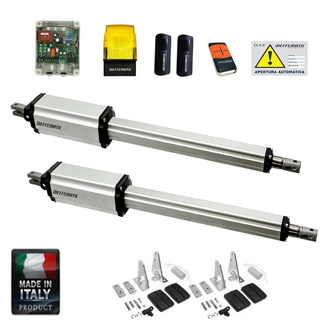
Figure 1: Dieffematic PM1 400 Swing Gate Automation Kit components. This image shows the main components included in the kit, typically two linear actuators and a control unit.
4. Konfiguracja i instalacja
The Dieffematic PM1 400 automation system is designed for straightforward installation without requiring modifications to your existing gate structure. The actuators feature a full metal frame and stainless steel rod for durability.
4.1 Kontrole przed instalacją
- Ensure your gate leaves are structurally sound and move freely without obstruction.
- Verify the gate dimensions and weight are within the system's specifications (up to 3.00 m length and 250 kg weight per leaf).
- Confirm availability of a 220V 50Hz power supply at the installation site.
4.2 Montaż siłowników
- Attach the rear mounting brackets to the gate pillars according to the provided template, ensuring correct alignment for the desired opening angle (maximum 100°).
- Attach the front mounting brackets to the gate leaves.
- Securely mount the two linear electromechanical actuators to the brackets.
4.3 Control Unit Installation and Wiring
- Mount the waterproof control unit box in a protected, accessible location near the gate.
- Connect the 220V 50Hz power supply to the control unit.
- Wire the two actuators to the control unit as per the wiring diagram in the detailed installation guide (not included in this general manual).
- Connect any optional safety devices (photocells, flashing light, pedestrian input) to the designated terminals on the control unit.
4.4 Konfiguracja początkowa
The control unit features an integrated receiver and electronic clutch with quick and comfortable stroke adjustment. It supports both symmetric and asymmetric gates by allowing independent management of each leaf's travel.
- Adjust the motor power and slowdown settings using the trimmers on the control unit.
- Configure the delay for the second gate leaf if desired.
- Set the desired operating logic: Step-by-step, Semi-automatic 1, Semi-automatic 2, or Automatic Condominium mode.
- The system includes obstacle detection and slowdown during opening and closing.
5. Instrukcja obsługi
5.1 Standardowa obsługa
- Use your remote control (paired with the integrated receiver) to open or close the gate.
- The gate will open/close with a smooth slowdown at the beginning and end of the movement.
5.2 Pedestrian Mode
If configured, a dedicated input allows for partial opening of one gate leaf for pedestrian access. Consult your installer for activation and usage.
5.3 Zwolnienie awaryjne
In case of power failure or malfunction, the gate can be manually operated using the emergency release key. The convenient key release mechanism is located on the motor unit. Insert the key and follow the instructions on the actuator to disengage the motor and manually move the gate leaves. The irreversible design ensures the gate remains locked in both open and closed positions without an electric lock.
6. Konserwacja
The Dieffematic PM1 400 automation system is designed for minimal maintenance. Once correctly installed, the system requires virtually no routine care due to its robust construction with an aluminum body and bronze gear core, ensuring a long lifespan.
- Periodically check for any obstructions in the gate's path.
- Ensure all mounting hardware remains secure.
- Keep photocells and safety sensors clean and unobstructed.
7. Rozwiązywanie Problemów
If you experience issues with your gate automation system, consider the following:
- Gate not responding: Check power supply, remote control battery, and ensure no safety devices are triggered (e.g., photocells blocked).
- Brama zatrzymuje się niespodziewanie: The obstacle detection system may have been activated. Check for obstructions in the gate's path.
- Niezwykłe dźwięki: Inspect the gate hinges and actuator mounting for any loose components or signs of wear.
For persistent problems, contact a qualified technician.
8. Specyfikacje
| Funkcja | Specyfikacja |
|---|---|
| Model | PM1 400 |
| Gate Leaf Length (Max) | 3.00m |
| Gate Leaf Weight (Max) | 250 kilogramów |
| Prędkość silnika | 1400 obr./min. |
| Moc | 280 W |
| Thrust Force (Adjustable) | 500 do 3000 N |
| Maksymalny kąt otwarcia | 100° |
| Zasilacz | 220 V 50 Hz |
| Actuator Weight (Approx.) | 6.0 kilogramów |
| ASIN | B07ZKM2CP5 |
| Numer referencyjny producenta | 264387266008 |
9. Gwarancja i wsparcie
For warranty information and technical support, please refer to the documentation provided with your purchase or contact your Dieffematic dealer. Keep your proof of purchase for warranty claims.