
1. Wprowadzenie
The DAOKI 5-Way Navigation Button Module (Model GR-US-036) provides a compact, multi-directional input solution for various electronic projects. This module integrates five directional controls (Up, Down, Left, Right, Middle Click) and additional Set and Reset buttons, making it suitable for MCU, AVR, Arduino, and gaming applications where a small, joystick-like control is required.
This manual provides essential information for the proper installation, operation, and maintenance of your navigation button module.
2. Zawartość opakowania
Sprawdź, czy w przesyłce znajdują się wszystkie elementy wymienione poniżej:
- 5 x Five-Direction Navigation Button Modules
- 1 x 8-Pin Female-to-Female Dupont Wire
- 1 x 8-Pin Female-to-Male Dupont Wire
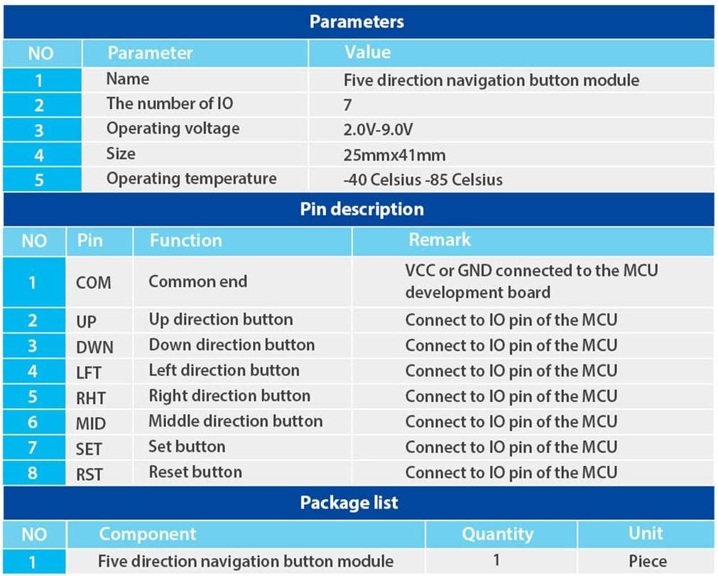
Rysunek 2.1: Table detailing module parameters, pin descriptions, and package contents.
3. Specyfikacje
The following are the technical specifications for the DAOKI 5-Way Navigation Button Module:
| Parametr | Wartość |
|---|---|
| Objętość operacyjnatage | 2.0 V - 9.0 V |
| Temperatura pracy | -40 °C do 85 °C |
| Wymiary (dł. x szer.) | 41 mm x 25 mm (1.61" x 0.98") |
| Number of IO Pins | 7 |
| Typ sterowania | 5-Way Directional (Up, Down, Left, Right, Middle Click) + Set + Reset |
| Typ złącza | Dupont Wire |
| Kompatybilne urządzenia | Microcontrollers (MCU), Arduino, Gaming Devices |
| Tworzywo | Copper, Plastic, Stainless Steel |
| Materiał kontaktowy | Złoto |
| Międzynarodowa Ocena Ochrony | IP54 |

Rysunek 3.1: Module dimensions for integration planning.
4. Opis pinów
The module features 8 pins for connection to a microcontroller or development board. Understanding each pin's function is crucial for correct wiring.
| Szpilka | Funkcjonować | Uwaga |
|---|---|---|
| KOM | Wspólny koniec | Connect to VCC or GND of the MCU development board. |
| UP | Przycisk kierunku w górę | Connect to an IO pin of the MCU. |
| DWN | Przycisk kierunku w dół | Connect to an IO pin of the MCU. |
| LFT | Przycisk kierunku w lewo | Connect to an IO pin of the MCU. |
| RHT | Right Direction Button | Connect to an IO pin of the MCU. |
| ŚREDNI | Middle Direction Button | Connect to an IO pin of the MCU. |
| USTAWIĆ | Ustaw przycisk | Connect to an IO pin of the MCU. |
| RST | Przycisk resetowania | Connect to an IO pin of the MCU. |

Rysunek 4.1: Szczyt view of the module with pin labels.

Rysunek 4.2: Module with joystick cap removed, showing the internal switch.

Rysunek 4.3: Spód view modułu.
5. Konfiguracja i instalacja
The installation of electronic modules requires basic knowledge of electronics and practical skills. Please proceed with caution.
5.1. Podłączenie zasilania
- Połącz KOM pin of the module to either the VCC (positive power supply) or GND (ground) of your MCU development board, depending on your circuit design and desired logic.
- Upewnij się, że napięcie zasilaniatage mieści się w określonym zakresie od 2.0 V do 9.0 V.
5.2. Data Pin Connection
- Połącz UP, DWN, LFT, RHT, ŚREDNI, USTAWIĆ, I RST pins of the module to individual digital input/output (IO) pins on your microcontroller (MCU).
- Use the provided Dupont wires for secure connections.

Rysunek 5.1: Example wiring diagram for connecting the module to a development board.
5.3. Montaż
The module is designed for panel mounting. Secure it using appropriate fasteners through the mounting holes on the PCB.
6. Instrukcja obsługi
Once correctly wired and powered, the module functions as a digital input device. Each button press (Up, Down, Left, Right, Middle, Set, Reset) will change the state of its corresponding IO pin on the MCU, which can then be read and processed by your program.
- Kontrola kierunkowa: Moving the joystick in any of the four cardinal directions (Up, Down, Left, Right) will activate the respective directional button.
- Kliknięcie środkowym przyciskiem: Pressing the joystick straight down activates the middle click function.
- Przycisk SET: The 'SET' button provides an additional input for configuration or menu selection.
- Przycisk RST: The 'RST' button can be used for reset functions or other programmed actions.
Refer to your microcontroller's programming environment and documentation for details on reading digital input states from the connected IO pins.
7. Konserwacja
The DAOKI 5-Way Navigation Button Module is designed for durability and requires minimal maintenance. Follow these guidelines to ensure its longevity:
- Czyszczenie: Keep the module free from dust and debris. Use a soft, dry cloth for cleaning. Avoid using liquids or abrasive cleaners.
- Środowisko: Operate the module within its specified temperature range (-40 °C to 85 °C). Avoid exposure to extreme humidity or corrosive environments.
- Obsługiwanie: Należy obchodzić się z modułem ostrożnie, aby zapobiec uszkodzeniu podzespołów lub połączeń lutowanych.
8. Rozwiązywanie Problemów
If you encounter issues with your DAOKI 5-Way Navigation Button Module, consider the following troubleshooting steps:
- Brak reakcji na przyciski:
- Verify all pin connections (COM, UP, DWN, LFT, RHT, MID, SET, RST) are secure and correctly wired to the MCU.
- Sprawdź napięcie zasilaniatage to ensure it is within the 2.0V-9.0V range.
- Confirm that your MCU code is correctly configured to read the digital input states from the connected IO pins.
- Test the module with a different set of Dupont wires to rule out faulty cables.
- Intermittent Button Response:
- Inspect solder joints on the module and your development board for any cold joints or shorts.
- Ensure there is no physical obstruction preventing full button travel.
- Check for electromagnetic interference if operating in a noisy electrical environment.
- Uszkodzenia fizyczne:
- If the module has been dropped or subjected to excessive force, internal components may be damaged. Visual inspection for cracks or bent pins is recommended.
If issues persist after following these steps, consult relevant online forums or resources for microcontroller projects, or contact the manufacturer for further assistance.
9. Gwarancja i wsparcie
Specific warranty information for the DAOKI 5-Way Navigation Button Module (Model GR-US-036) was not provided in the product data. For details regarding warranty coverage, technical support, or replacement parts, please refer to the retailer's return policy or contact DAOKI directly through their official channels.