
1. Wprowadzenie
This manual provides essential information for the safe and efficient operation of your DEWIN AT1-2200X Variable Frequency Drive (VFD). This VFD is designed to convert single-phase 220V AC input into three-phase output, suitable for controlling 2.2kW three-phase asynchronous motors. Please read this manual thoroughly before installation and operation to ensure proper usage and to prevent damage or injury.
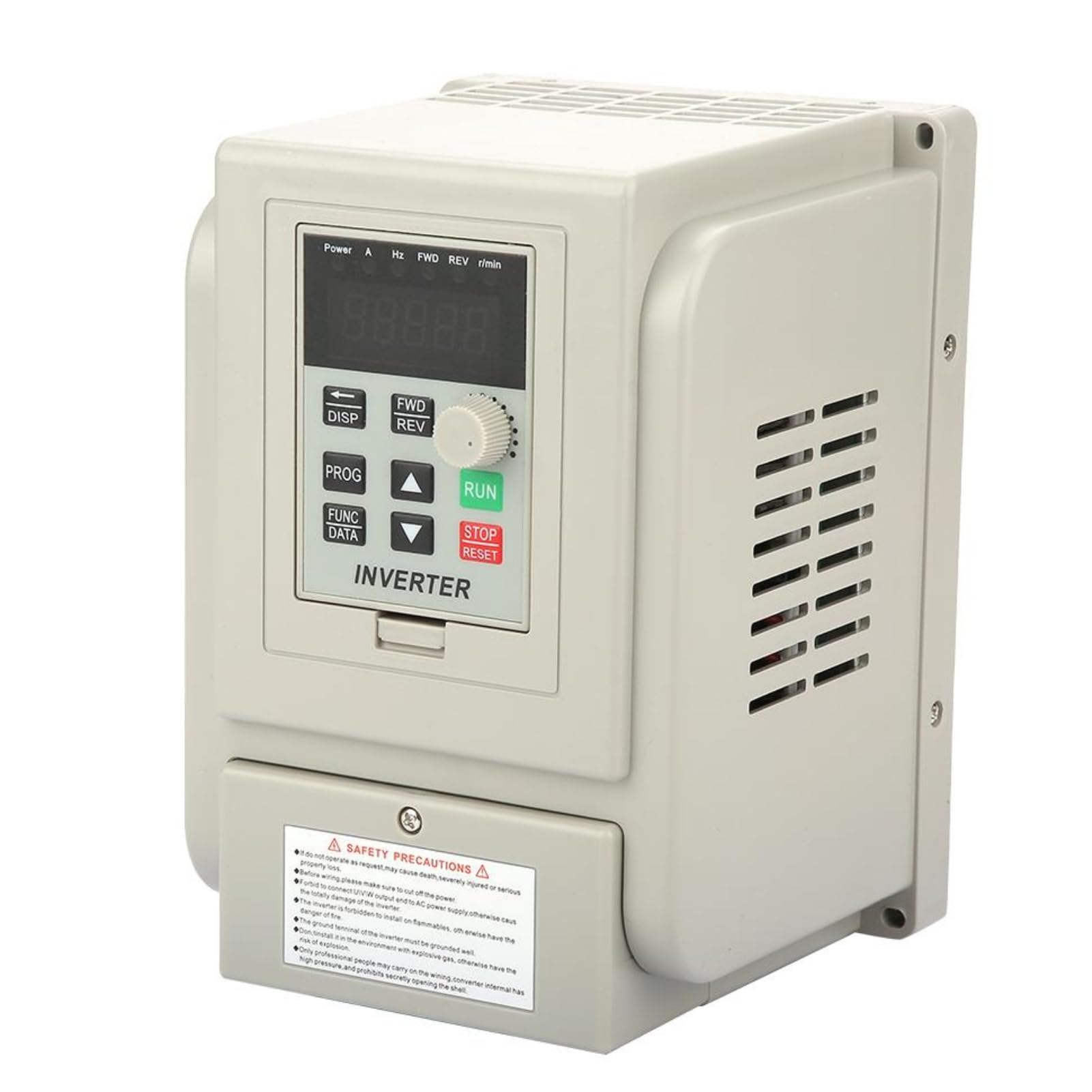
Rycina 1: Przód view of the DEWIN AT1-2200X VFD, showing the control panel and safety label.
Główne cechy:
- Wielorakie funkcje ochronne: Includes protection against overcurrent, overvoltage, podobjtage, module failure, overheating, short circuit, input/output phase loss, and more.
- Doskonała wydajność: Achieves high torque, high precision, and a wide range of driving speeds with quick start/stop response and high torque at low speeds.
- Stabilna praca: Features good anti-trip performance and adaptability to power supply fluctuations, temperature, humidity, and dust. Equipped with a large heatsink for efficient heat dissipation.
- Anti-interference Capability: Optimized PWM control technology and electromagnetic compatibility reduce noise and electromagnetic interference.
- Proste okablowanie: Connections are made via screw terminals for straightforward installation.
2. Środki ostrożności
OSTRZEŻENIE: Nieprzestrzeganie tych instrukcji bezpieczeństwa może spowodować porażenie prądem, pożar, poważne obrażenia lub uszkodzenie mienia.
- Always read this manual carefully before operating the VFD.
- Przed przystąpieniem do wykonywania jakichkolwiek prac okablowania lub prac konserwacyjnych należy upewnić się, że zasilanie jest odłączone.
- Only qualified personnel should perform wiring and installation to avoid electric shock or fire.
- Do not install the inverter in environments with flammable materials.
- The ground terminal of the inverter must be reliably grounded.
- Avoid touching the inverter terminals immediately after disconnecting power, as residual voltage może być obecny.

Figure 2: Safety precautions label on the VFD unit.
3. Konfiguracja i okablowanie
Proper wiring is crucial for the safe and correct operation of the VFD. Refer to the wiring diagram below for connections.

Rysunek 3: Schemat okablowania instalacyjnego.
Połączenia terminalowe:
| Terminal | Funkcjonować | Bliższe dane |
|---|---|---|
| 15 V/24 V | Wejście/wyjście zasilania | 15V/24V power input, 200mA/15V/24V power supply output. |
| X6 | Input Terminal 6 | Wire control CW/CCW. Connects to COM for effective input signal. |
| X5 | Input Terminal 5 | Wire control CCW. Connects to COM for effective input signal. |
| X4 | Input Terminal 4 | Wire control CW. Connects to COM for effective input signal. |
| X3 | Input Terminal 3 | Speed range 3. Connects to COM for effective input signal. |
| X2 | Input Terminal 2 | Speed range 2. Connects to COM for effective input signal. |
| X1 | Input Terminal 1 | Speed range 1. Connects to COM for effective input signal. |
| KOM | Wspólny terminal | Common terminal for control signals. |
| VI1 | External Analog Voltage Wejście | 0-5V/10V analog voltage wejście. |
| SP1 | Wyjście typu otwarty kolektor 1 | |
| SP2 | Wyjście typu otwarty kolektor 2 | |
| 5 V/10 V | Wyjście zasilacza | 5V/10V 20mA power supply output. |
Ensure all connections are secure and correctly matched to your motor and power supply specifications. The VFD requires a single-phase 220V input and provides a three-phase output for the motor.

Rysunek 4: Tył view showing power terminals (L, N, W, V, U).
4. Instrukcja obsługi
The DEWIN AT1-2200X VFD features an intuitive control panel for easy operation. Familiarize yourself with the buttons and display functions.

Figure 5: Control Panel Buttons.
Funkcje panelu sterowania:
- 5-cyfrowy wyświetlacz LED: Shows current operating parameters and settings.
- DISP (Movement Key): Used to switch between monitoring parameters in the monitoring state or to move the data frame to edit bits in the second-level menu.
- PROG (Programme Key): Exits the current operating state and switches to other states, primarily used to enter the monitoring state.
- FUNC/DATA (Function/Save Key): Enters the menu step-by-step and saves the configured parameters.
- ▼ (Minus Key): A short or long press decreases data values or function codes.
- ▲ (Plus Key): A short or long press increases data values or function codes.
- FWD/REV (CW/CCW Key): Press to run the motor in the forward direction (CW). Release to stop. Can also be configured for counter-clockwise (CCW) operation.
- STOP/RESET (Stop/Reset Key): Stops the VFD operation and can be used to recover from a previous error interface.
- RUN (Operation Key): Initiates the VFD operation.
5. Specyfikacje
Below are the technical specifications for the DEWIN AT1-2200X Variable Frequency Drive:
| Parametr | Wartość |
|---|---|
| Marka | DEWIN |
| Numer modelu | AT1-2200X |
| Wejście Voltage | Single-phase 220V AC |
| Objętość wyjściatage | Three-phase 220V AC |
| Moc znamionowa | 2.2 kW |
| Wymiary (dł. x szer. x wys.) | Wymiary: 18 cm x 31.8 cm x 12.5 cm |
| Waga | 1283 gram |
| Źródło zasilania | Cable Electric |
| GTIN / UPC | 723645761883 |

Figure 6: DEWIN AT1-2200X VFD units showing dimensions.
6. Konserwacja
Regular maintenance helps ensure the longevity and reliable performance of your VFD.
- Czyszczenie: Periodically clean the exterior of the VFD with a soft, dry cloth. Ensure ventilation openings are free from dust and debris to maintain proper airflow for cooling.
- Kontrola połączenia: Regularly inspect all wiring connections for tightness and signs of wear or corrosion. Loose connections can lead to overheating or intermittent operation.
- Warunki środowiskowe: Ensure the VFD is operated within its specified environmental conditions (temperature, humidity, dust levels) to prevent premature failure.
- Inspekcja profesjonalna: For complex issues or internal inspections, it is recommended to consult a qualified technician.

Rysunek 7: Wewnętrzne view showing heatsink and cooling fans.
7. Rozwiązywanie Problemów
If you encounter issues with your VFD, refer to the following basic troubleshooting steps:
- Brak zasilania: Check the main power supply and all input wiring connections. Ensure the circuit breaker or fuse is not tripped.
- Silnik nie pracuje: Verify that the RUN command is active and that the motor is correctly wired to the VFD output terminals. Check for any error codes on the LED display.
- Nadprąd/Przeciążenie: Reduce the motor load or check for mechanical issues with the motor. Verify that the VFD's current limits are set appropriately for your motor.
- Przegrzanie: Ensure adequate ventilation around the VFD. Clean any dust from the heatsink and fans. Check ambient temperature.
- Wyświetlane błędy: If an error code appears, consult the full product manual (if available) for specific code meanings and resolutions. Try pressing the STOP/RESET key to clear temporary errors.
For persistent issues or complex problems, contact customer support or a qualified electrician.
8. Gwarancja i wsparcie
For warranty information, technical support, or service inquiries, please refer to the documentation included with your purchase or contact your retailer. Keep your purchase receipt as proof of purchase for warranty claims.
