
1. Wprowadzenie
This manual provides detailed instructions for the installation, operation, and maintenance of your Alomejor 48V 500W Brushed DC Motor Speed Controller. This controller is designed to provide stable speed and sensitive control for braking and direction changes in various applications, including e-bikes, scooters, golf carts, and light industrial machinery. Please read this manual thoroughly before use to ensure proper function and safety.
2. Informacje dotyczące bezpieczeństwa
Aby zapobiec obrażeniom ciała lub uszkodzeniu produktu, należy zawsze przestrzegać następujących środków ostrożności:
- Ensure the power supply is disconnected before performing any installation, wiring, or maintenance.
- Sprawdź, czy objętośćtage i cotage of your motor and battery are compatible with this 48V 500W controller.
- Avoid short circuits by ensuring all connections are secure and properly insulated.
- Do not expose the controller to water, excessive moisture, or extreme temperatures.
- Mount the controller in a location that allows for adequate heat dissipation.
- Jeśli nie jesteś pewien, który etap instalacji należy wykonać, skonsultuj się z wykwalifikowanym technikiem.
3. Funkcje produktu
- Materiał Premium: The controller shell is constructed from aluminum alloy, which protects the internal circuitry and aids in heat dissipation to prevent thermal overloading.
- Brushed Motor Controller: Provides steady speed control and sensitive response for braking and direction changes.
- Łatwa instalacja: Interfaces are clearly labeled with instructions for straightforward setup.
4. Specyfikacje
| Funkcja | Szczegół |
|---|---|
| Marka | Alomejor |
| Model | YK31C |
| Tomtage | 48 wolty |
| Horsepower / Wattage | 500 watów |
| Tworzywo | Aluminium |
| Waga przedmiotu | 0.19 kilograma (ok. 6.7 uncji) |
| Wymiary (w przybliżeniu) | 83 mm (długość) x 65 mm (szerokość) x 37 mm (wysokość) |
| UPC | 798382614525 |
Uwaga: wymiary są przybliżone i mogą się nieznacznie różnić.

Figure 1: Controller dimensions (83mm x 65mm x 37mm).
5. Konfiguracja i instalacja
The controller features clearly labeled interfaces for easy connection. Refer to the diagram below for typical wiring connections. Always ensure power is off before connecting or disconnecting any wires.
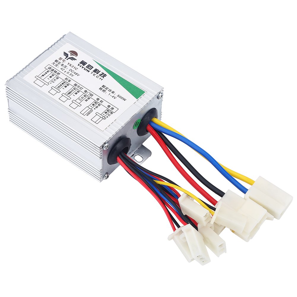
Figure 2: Controller with labeled wiring harness.

Rysunek 3: Szczegółowy view złączy kontrolera.
Instrukcje okablowania:
- Podłączenie akumulatora: Connect the main power wires (usually thicker red for positive and black for negative) from your 48V battery to the corresponding battery input terminals on the controller.
- Podłączenie silnika: Connect the motor wires to the motor output terminals. Ensure correct polarity if specified by your motor.
- Połączenie przepustnicy: Connect the throttle unit to the designated throttle input port. This typically involves three wires: power, ground, and signal.
- Brake Lever Connection: Connect the brake lever wires to the brake input port. This allows the controller to cut power to the motor when the brakes are applied.
- Charging Port (if applicable): If your system includes a dedicated charging port, connect it to the controller's charging input.
- Indicator Lights/Other Accessories: Connect any additional accessories like indicator lights or power locks to their respective labeled ports.
- Bezpieczne mocowanie: Mount the controller securely in a location that is protected from physical damage and allows for proper airflow to prevent overheating.
After all connections are made, double-check them for security and correctness before applying power.
6. Instrukcja obsługi
Once the controller is correctly installed and all connections are secure:
- Turn on the main power switch for your system (if present).
- The controller will typically enter a standby mode.
- Engage the throttle to activate the motor. The speed will increase proportionally with the throttle input.
- Applying the brakes should cut power to the motor, allowing for safe stopping.
- Always operate your vehicle or machinery responsibly and within its intended limits.
7. Konserwacja
To ensure the longevity and optimal performance of your motor speed controller, follow these maintenance guidelines:
- Regularna kontrola: Periodically check all wiring connections for looseness, corrosion, or damage. Tighten any loose connections.
- Czystość: Keep the controller free from dust, dirt, and debris. Use a soft, dry cloth to wipe the exterior. Do not use liquid cleaners directly on the controller.
- Ochrona środowiska: Ensure the controller remains protected from water, extreme humidity, and direct sunlight.
- Zarządzanie ciepłem: Verify that the mounting location allows for adequate ventilation to prevent overheating, especially during prolonged use.
- Unikaj wpływu fizycznego: Protect the controller from drops or impacts that could damage its internal components or aluminum casing.
8. Rozwiązywanie Problemów
Jeśli napotkasz problemy z kontrolerem, zapoznaj się z poniższymi typowymi problemami i rozwiązaniami:
| Problem | Możliwa przyczyna | Rozwiązanie |
|---|---|---|
| Silnik nie działa | No power to controller; Loose connections; Faulty throttle; Overload protection activated. | Check battery charge and connections; Inspect all wiring; Test throttle functionality; Reduce load or allow controller to cool. |
| Silnik pracuje z przerwami | Loose wiring; Intermittent throttle signal; Overheating. | Secure all connections; Check throttle wiring; Ensure adequate ventilation. |
| Controller gets excessively hot | Overload; Insufficient ventilation; Short circuit in motor or wiring. | Reduce load; Improve airflow around controller; Inspect motor and wiring for shorts. |
| Brakes do not cut power | Brake lever switch faulty; Brake wiring disconnected. | Check brake lever switch; Verify brake wiring connections. |
Jeśli po wypróbowaniu tych rozwiązań problem nadal występuje, skontaktuj się z obsługą klienta.
9. Gwarancja i wsparcie
Alomejor is committed to providing high-quality products. If you are not satisfied with the product you received, you may contact us via email at any time. We will respond promptly and assist you in resolving your issue.
For further assistance or technical support, please refer to the contact information provided with your purchase or visit the official Alomejor store page on Amazon: Alomejor Store.